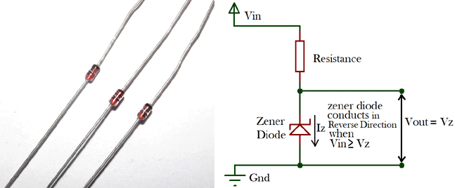
Introduction
Diodes generally are known as a device that allows the flow of current in one direction (forward biased) and offers resistance to the flow of current when used in reverse bias. Zener Diode (Named after the American scientist C. Zener who first explained its operational principles) on the other hand, not only allow the flow of current when used in forward bias, but they also allow the flow of current when used in the reversed bias so far the applied voltage is above the breakdown voltage known as the Zener Breakdown Voltage. Or in other words Breakdown voltage is the voltage, on which Zener Diode starts conducting in reverse direction.
Operational Principle of Zener Diode:


In normal diodes, the breakdown voltage is very high and the diode gets damaged totally if a voltage above the breakdown diode is applied, but in Zener diodes, the breakdown voltage is not as high and does not lead to permanent damage of the zener diode if the voltage is applied.
As the reverse voltage applied to the Zener diode increases towards the specified Breakdown Voltage (Vz), a current starts flowing through the diode and this current is known as the Zener Current and this process is known as Avalanche Breakdown. The current increases to a maximum and get stabilized. This current remains constant over the wider range of applied voltage and allows the Zener diode to withstand with higher voltage without getting damaged. This current is determined by the series resistor.
Consider the Images below of a normal diode in action.
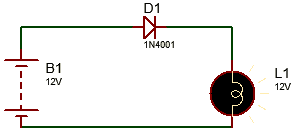
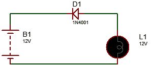
To show the operations of the zener diode, consider the two experiments (A and B) below.
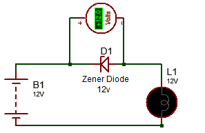
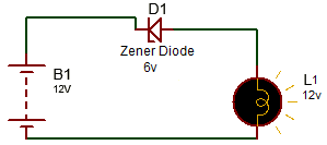
In Experiment A, a 12V zener diode is connected in reversed biased as shown in the image and it can be seen that the zener diode blocked the voltage effectively because it was less/equal to the breakdown voltage of the particular zener diode and the lamp thus stayed off.
In Experiment B, a 6v Zener Diode used is conducting (the bulb comes on) in reverse biased because the applied voltage is greater than its breakdown voltage and thus shows that the breakdown region is the region of operation of the zener diode.
The current-voltage characteristic curve of the Zener diode is shown below.
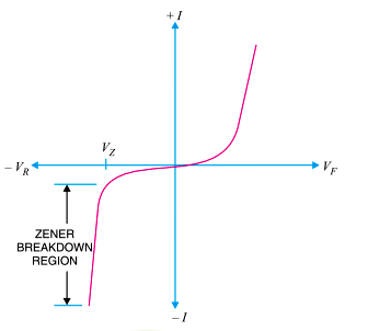
From the graph, it can be deduced that the zener diode operated in the reverse bias mode will have a fairly constant voltage irrespective of the amount of current supplied.
Applications of Zener Diode:
Zener diodes are used in three main applications in electronic circuits;
1. Voltage Regulation
2. Waveform Clipper
3. Voltage Shifter
1. Zener Diode as Voltage Regulator
This is arguably the most common application of zener diodes.
This application of the zener diodes relies heavily on the ability of the zener diodes to maintain a constant voltage irrespective of variations in supply or load current. The general function of a voltage regulation device is to provide a constant output voltage to a load connected in parallel to it irrespective of variations in the energy drawn by the load (Load current) or variations and instability in the supply voltage.
The Zener diode will provide constant voltage provided current stays within the range of the maximum and minimum reverse current.
The circuit diagram showing the Zener diode being used as a Voltage regulator is shown below.
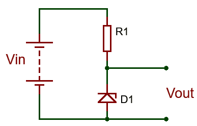
A resistor, R1 is connected in series with the zener diode to limit the amount of current flowing through the diode and the input voltage Vin (Which must be greater than the zener voltage) is connected across as shown in the image and the output voltage Vout, is taken across the zener diode with Vout = Vz (Zener Voltage). Since the zener diode’s reverse bias characteristics are what is needed to regulate the voltage, it is connected in reversed bias mode, with the cathode being connected to the positive rail of the circuit.
Care must be taken when selecting the value of resistor R1, as a small value resistor will result in a large diode current when the load is connected and this will increase the power dissipation requirement of the diode which could become higher than the maximum power rating of the zener and could damage it.
The value of resistor to be used can be determined using the formula below.
R1 = (Vin – VZ) / IZ

Where;
R1 is the value of the series resistance.
Vin is the input voltage.
Vz which is same as Vout is the Zener voltage
And Iz is the zener current.
By using this formula it becomes easy to ensure that the value of the resistor selected doesn’t lead to the flow of current higher than what the zener can handle.
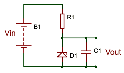
One little problem experienced with zener diode based regulator circuits is that the Zener sometimes generate electrical noise on the supply rail while making attempts to regulate the input voltage. While this may not be a problem for most applications, this problem may be solve by the addition of a large value decoupling capacitor across the diode. This helps stabilize the output of the zener.
2. Zener Diode as Waveform Clipper
One of the uses of normal diodes is in the application of clipping and clamping circuits which are circuits that are used to shape or modify an input AC waveform or signal, producing a differently shaped output signal depending on the specifications of the clipper or clamper.
Clippers circuits generically are circuits that are used to prevent the output signal of a circuit from going beyond a predetermined voltage value without changing any other part of the input signal or waveform.
These circuits along with clampers are widely used in Analog television and FM radio transmitters for the removal of interference (clamping circuits) and limiting noise peaks by clipping of high peaks.
Since Zener diodes generically behave like normal diodes when the applied voltage is not equal to the breakdown voltage, they are also thus used in clipping circuits.
Clipping circuits could be designed to clip the signal either in the positive, negative or both regions. Although the diode will naturally clip off the other region at 0.7V irrespective of whether it was designed as a positive or negative clipper.
For example, consider the circuit below.
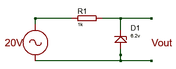
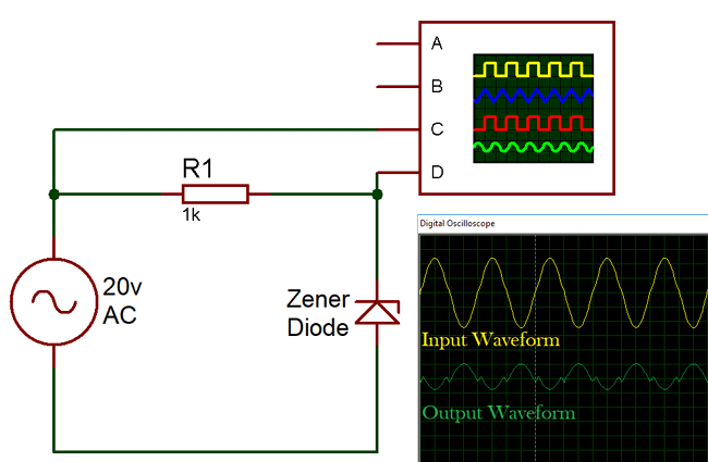
The clipper circuit is designed to clip the output signal at 6.2v, so a 6.2v zener diode was used. The zener diode prevents the output signal from going beyond the zener voltage irrespective of the input waveform. For this particular example, a 20v input voltage was used and the output voltage on the positive swing was 6.2v consistent with the voltage of the zener diode. During the negative swing of the AC voltage however, the zener diode behaves just like the normal diode and clips the output voltage at 0.7V, Consistent with normal silicone diodes.
To implement the clipping circuit for the negative swing of the AC circuit as well as the positive swing in such a way that the voltage is clipped at different levels on the positive and negative swing, a double zener clipping circuit is used. The circuit diagram for the double zener clipping circuit is shown below.
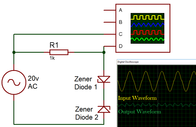
In the clipping circuit above, the voltage Vz2 represents the voltage on the negative swing of the AC source at which the output signal is desired to be clipped, while voltage Vz1 represents the voltage on the positive swing of the AC source at which the output voltage is desired to be clipped.
3. Zener Diode as Voltage Shifter
The voltage shifter is one of the simplest but interesting applications of the zener diode. If you have had experience especially with connecting a 3.3v sensor to a 5V MCU, and have seen first-hand the errors in readings, etc, that this can lead to them you will appreciate the importance of voltage shifters. Voltage shifters help convert signal from one voltage to another and with the ability of the zener diode to maintain steady output voltage in the breakdown region, it makes them Ideal component for the operation.
In a zener diode based voltage shifter, the circuit, lowers the output voltage, by a value equal to the breakdown voltage of the particular zener diode that is used. The circuit diagram for the voltage shifter is illustrated below.
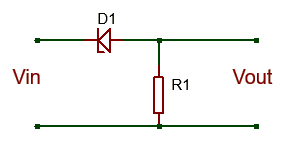
Consider the experiment below,
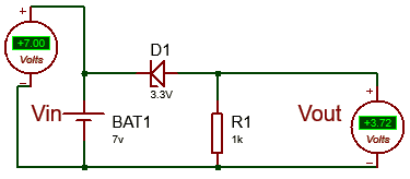
The circuit describes a 3.3v zener diode based voltage shifter. The output voltage (3.72V) of the circuit is given by subtracting the breakdown voltage (3.3V) of the zener diode from the input voltage (7V).
Vout = Vin –Vz
Vout = 7 – 3.3 = 3.7v
The voltage shifter as describe earlier on has several applications in modern day electronic circuits design as the design engineer may have to work with up to three different voltage level at times during design process.
Types of Zener Diodes:
Zener diodes are categorized into types based on several parameters which include;
- Nominal Voltage
- Power Dissipation
- Forward drive current
- Forward voltage
- Packaging type
- Maximum Reverse Current
Nominal Voltage
The nominal Operation voltage of a zener diode is also known as the breakdown voltage of the zener diode, depending on the application for which the diode is to be used, this is often the most important criteria for Zener diode selection.
Power dissipation
This represents the maximum amount of power the zener current can dissipate. Exceeding this power rating leads to excessive increase in the temperature of the zener diode which could damage it and lead to the failure of the things connected to it in a circuit. Thus this factor should be considered when selecting the diode with the use in mind.
Maximum Zener Current
This is the maximum current that can be passed through the zener diode at the zener voltage without damaging the device.
Minimum Zener Current
This refers to the minimum current required for the zener diode to start operating in the breakdown region.
Other parameters that serve as the specification for the diode all need to be fully considered before a decision is made on the type on the kind of zener diode needed for that peculiar design.
Conclusion:
Here are 5 points you should never forget about the zener diode.
- A zener diode is like an ordinary diode only that it has been doped to have a sharp a breakdown voltage.
- The Zener diode maintains a stable output voltage irrespective of the input voltage provided the maximum zener current is not exceeded.
- When connected in forward bias, the zener diode behaves exactly like the normal silicone diode. It conducts with the same 0.7v voltage drop that accompanies the use of the normal diode.
- The zener diode default operational state is in the breakdown region (reversed biased). It means it actually starts to work when the applied voltage is higher than Zener Voltage in reverse biased.
- The zener diode is mostly used in applications involving, voltage regulation, clipping circuits and Voltage shifters.
Yaaaaaga!!!
I don't think I want to understand the article doe, but I gat brotherly love for the writter! Gbam!
zener diode concept
Good explanation, well understanding manner.


Very informative article. Well laid out and well written. :)