Here we are going to establish a communication between an ATmega8 microcontroller and Arduino Uno. The communication established here is UART (Universal Asynchronous Receiver Transmitter) type. It’s serial communication. By this serial communication data can be shared between two controllers, which is a required in various embedded system applications.
In embedded systems we must have basic knowledge about system communications, so for this we are doing this project. In this project we will discuss basic communication system and we will send some data from transmitter to receiver in serial.
[Also check: UART communication between two ATmega controllers]
In this project ATMEGA8 acts as a TRANSMITTER and ARDUINO UNO acts as a RECECIVER. In serial communication we will send data BIT BY BIT, until a BYTE of data is transferred completely. The data can be of 10bit size but we will keep to 8BITS for now.
Components Required
Hardware: ATMEGA8, ARDUINO UNO, power supply (5v), AVR-ISP PROGRAMMER, 100uF capacitor (connected across power supply), 1KΩ resistor (two pieces), LED , Button.
Software: Atmel studio 6.1, progisp or flash magic, ARDUINO NIGHTLY.
Circuit Diagram and Explanation
Before we discuss the circuit diagram and programming for transmitter and receiver, we need to understand about the serial communication. The ATMEGA here sends data to the UNO in serial as discussed earlier.
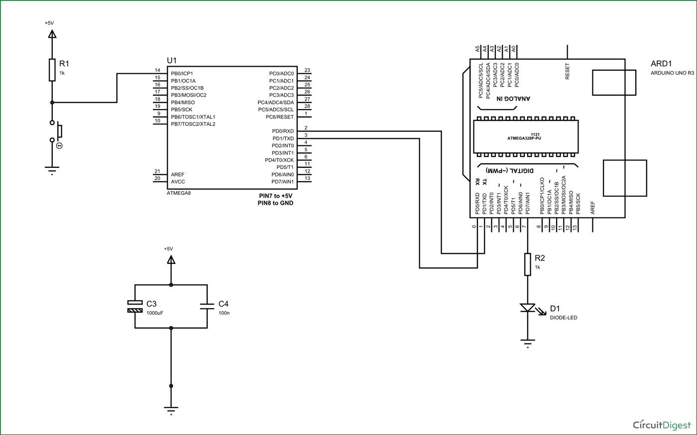
It has other modes of communication like MASTER SLAVE communication, JTAG communication but for easy communication we are choosing RS232. Here we will connect the TXD (Transmitter) PIN of ATMEGA8 to RXD (Receiver) PIN of ARDUINO UNO
The data communication established is programmed to have:
- Eight data bits
- Two stop bits
- No parity check bit
- Baud rate of 9600 BPS(Bits Per Second)
- Asynchronous communication(No clock share between ATMEGA8 and UNO (both have different clock units))
For establishing UART between Arduino Uno and ATMEGA8 we need to program the setting accurately. For this we need to keep the above mentioned parameters same at both ends. In this one acts as TRANSMITTER and other acts as RECEIVER. We will discuss each side settings below.
Now for the RS232 interface, the following features must be satisfied for the TRANSMITTER side (ATMEGA8):
1. The TXD pin (data receiving feature) of first controller must be enabled for TRANSMITTER.
2. Since the communication is serial we need to know whenever the data bye is received, so that we can stop the program until complete byte is received. This is done by enabling a data receive complete interrupt.
3. DATA is transmitted and received to controller in 8bit mode. So two characters will be sent to the controller at a time.
4. There are no parity bits, one stop bit in the data sent by the module.
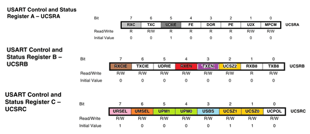
The above features are set in the controller registers; we are going to discuss them briefly:

DARK GREY (UDRE): This bit not set during startup but it is used during working to check whether transmitter is ready to transmit or not. See the program on TRASMITTER SIDE for more details.
VOILET (TXEN): This bit is set for enabling transmitter pin on TRASMITTER SIDE.
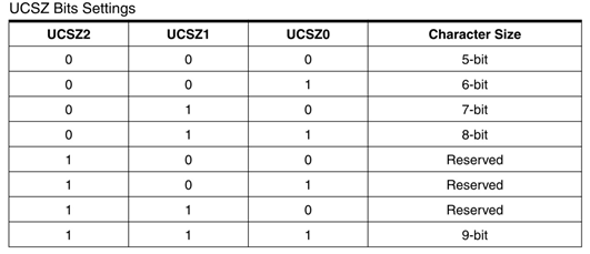
YELLOW (UCSZ0, UCSZ1, and UCSZ2): These three bits are used for selecting the number of data bits we are receiving or sending in a single go.

The communication between two SIDES is established as eight bit communication. By matching the communication with table we have, UCSZ0, UCSZ1 to one and UCSZ2 to zero.
ORANGE (UMSEL): This bit is set based on whether the system is communicating asynchronously (both use different clock) or synchronously (both use same clock).

Both the SYTEMS do not share any clock. Since both of them use internal clock of their own. So we need to set UMSEL to 0 in both controllers.
GREEN (UPM1, UPM0): These two bits are adjusted based on bit parity we are using in communication.

The data ATMEGA here is programmed to send data with no parity, as the data transmission length is small, we can clearly expect no data loss or error. So we are not setting any parity here. So we set both UPM1, UPM0 to zero or they are left, because all bits are 0 by default.
BLUE (USBS): This bit is used for choosing the number of stop bits we are using during communication.

The communication established her is of asynchronous type, so for getting more accurate data transmission and reception, we need to use two stop bits, Hence we set USBS to ‘1’ in TRANSMITTER side..
The baud rate is set in controller by choosing the appropriate UBRRH:

The UBRRH value is chosen by cross referring baud rate and CPU crystal frequency:

So by cross reference UBRR value is seen as ‘6’, and so the baud rate is set.
With this we have established settings on TRANSMITTER SIDE; we will talk about RECEIVING SIDE now.
The serial communication enabling in UNO can be done by using a single command.
|
The communication we presumed to establish is done by a BAUD rate of 9600 bits per second. So for UNO to establish such baud rate and to start serial communication we use command ”Serial.begin(9600);”. Here 9600 is baud rate and is changeable.
Now all left if to receive data, one a data is received by the UNO, it will be available for taking. This data is picked up by command “receiveddata = Serial.read();”. By this command serial data is taken to ‘receiveddata’ named integer.
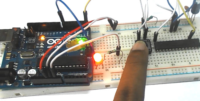
As shown in circuit a button in connected on transmitter side, when this button in pressed an eight bit data is sent by TRANSMITTER (ATMEGA8) and this data is received by RECEIVER (ARDUINO UNO). On receiving this data successfully it toggles the LED connected to it ON and OFF, to show successful data transfer between two controller.
By this UART communication between ATMEGA8 controller and ARDUINO UNO is successfully established.
Complete Project Code
PROGRAM ON TRANSMITTER SIDE:
#include <avr/io.h>
//header to enable data flow control over pins
#define F_CPU 1000000UL
//telling controller crystal frequency attached
#include <util/delay.h>
//header to enable delay function in program

int main(void)
{
                DDRB =0;//PORTB is set as INPUT
                DDRD |= 1 << PIND1;//pin1 of portD as OUTPUT
                DDRD &= ~(1 << PIND0);//pin0 of portD as INPUT
                PORTD |= 1 << PIND0;

                int UBBRValue = 6;//AS described before setting baud rate 9600BPS

                //Put the upper part of the baud number here (bits 8 to 11)
                UBRRH = (unsigned char) (UBBRValue >> 8);

                //Put the remaining part of the baud number here
                UBRRL = (unsigned char) UBBRValue;

                //Enable the receiver and transmitter
                UCSRB = (1 << RXEN) | (1 << TXEN);

                //Set 2 stop bits and data bit length is 8-bit
                UCSRC = (1 << USBS) | (3 << UCSZ0);

                while (1)
                {
                                if (bit_is_clear(PINC,0))//once button is pressed
                                {

                                                while (! (UCSRA & (1 << UDRE)) );
                                                {
                                                                UDR = 0b11110000;//once transmitter is ready sent eight bit data
                                                }
                                                _delay_ms(220);
                                }

PROGRAM ON RECEIVER SIDE:
int receiveddata =0;
void setup()
{
                Serial.begin(9600);//serial data rate is set for 9600BPS
                pinMode(0,INPUT);//RXD pin is set for INPUT
                pinMode(1,OUTPUT);
                pinMode(7,OUTPUT);//PIN1,PIN7 are set for output

}
void loop()
{
                if (Serial.available() > 0) //if data received is available
                {
        receiveddata = Serial.read();//read serial data available
                                if (receiveddata == 0)//compare the data received
                                {
                                                PORTD^=(1<<7);//id data matches toggle the LED.
                                }
                }
}
Comments
Ur Tx code is either incomplete or incorrect.
Wat ur code does and wat ur video shows are completely different.
I need some help in Sending data from an ARDUINO UNO and receiving on ATMEGA32
Could you please help me with that.
Thank You
I have the same problem as Rashmitha, I like to be able to send from Arduino and receive by Atmega32 and be able to toggle the duty . ie. some time being transmitter and some other time as receiver.
please help in this regard.
I would like to send a char from an arduino Uno to a Atmega1284 using USART. Can you please help?


Hi, i was wondering if it's possible to do the opposite,
I have an arduino Uno where i wish to send Analog read to an atmega16 to display it on the screen how can i prepare the atmega to receive the data if more than one digit. and the uart settings.