

Just like the craze for Pokémon Go out of nowhere the fidget spinners got popular and it became more of trend to have one of these spinning between your fingers. But lately people (including me) eventually got bored of it and hence in this project let us bring in a new purpose for fidget spinner by building a simple motor using Fidget Spinner. With this circuit you will be able to make the fidget spinner rotate forever with the help of basic physics and not worry about having it idle at some corner of your room. You will also learn the basic of how a Brushless DC motor works since the concept we are using here is same as that used in the famous BLDC motors. Sounds interesting enough??? Let’s get started...
Materials Required:
- Fidget Spinner
- 12V Electromagnet
- Neodymium magnets
- 12V DC adapter
- 7805 Voltage Regulator
- 1N4007 Diode
- Resistors (1K and 10K)
- LED
- Hall sensor (US1881)
- Connecting wires
- Breadboard
- Arrangement to hold spinner and electromagnet
How to make Fidget Spinner Rotate Indefinitely?
This project is simple and easy to build if you understand the concept behind its working, which we are going to discuss now. So as we said earlier we are going to use the same concept that is being used in BLDC motors. BLDC motors are very famous and find its vital application in Drones, RC cares and mainly in Electric vehicles. These motors uses hall sensors instead of normal brushes, hence the iconic name Brushless DC motor. I do not want to get too deep on its working but here I am briefly explaining about how BLDC motor works. In BLDC (hub type) motor the stator would will windings which forms the electromagnet and the rotor will have permanent magnets. A sensor called hall sensor is used to sense the polarity of the magnet that is opposite to the electromagnet and use that information to trigger the electromagnet with same polarity. As we know like poles repels and the hence the electromagnet will push the permanent magnet away causing it to rotate. This sequence will be repeated and the hall sensor will read for magnets polarity and trigger the electromagnet in an orderly fashion to keep the rotor rotating.
Now, coming to our project of Turning a Fidget Spinner into Brushless Motor. Here, the fidget spinner is the Rotor. Since a normal fidget spinner does not have any magnet we would have to fix magnets to the fidget spinner. Make sure you use only neodymium magnets and also ensure that all the magnets facing up or of the same pole. You can do that by using another magnet, my spinner had a metal piece at the end and hence it was easy to stick the magnets and it looked like this below. I have also removed the centre casing to expose the ball bearing.

The rotor is now ready with magnets, next we need an electromagnet to be placed directly under the magnets path so that we can repel the magnets. Mine is a 12V electromagnet, power yours and bring it close to all thee magnets to ensure that they are rippling each other. Now we need to sense when the magnet is on top of the electromagnet and trigger it only then. Once the magnet is rippled we should turn off the electromagnet for the fidget spinner to rotate freely and again turn on the electromagnet when it experience a neodymium magnets above it, and that’s how you will get a fidget spinner that spins for every detection. This detection and triggering can be achieved using the circuit below.
Circuit Diagram and Explanation:
The complete circuit diagram for Fidget Spinner Motor Project is given below, the responsibility of each component in the circuit is explained further below.

12V DC adapter: The need for 12V in this project is that the Electromagnet works with 12V only. It also consumes about 330mA curreant and hence I have chosen a 12V 1A DC adapter as the power source.
7805 Voltage Regulator: The source for this project is 12V but we need a regulated 5V for the Hall sensor and L293D module hence we use a 7805 to convert the 12V to 5V.
L293D Motor Driver: As told earlier we have to turn on and turn off the electromagnet rapidly based on the position of the magnet on fidget spinner. A L293D is normally used to drive motors but it can also be used in our application for driving the electromagnet. It takes input from the hall sensor and based on that input it turns on or turns off the electromagnet. We will be using only one electromagnet and hence the other section is left free.
Hall Sensor: The hall sensor is used to check if the magnet is directly on top of the electromagnet, only if it is there it will energise the electromagnet through L293D; else the electromagnet will be kept turned off. Know more about Hall sensor and its interfacing with Arduino.
Resistor 10k: The 10K resistor is used to pull high the output pin of the Hall sensor, this resistor is mandatory else the output pin will of the sensor will be left floating.
Resistor 1K and LED: The resistor in combination with LED is used to indicated if the hall sensor is detecting the magnet or not. If magnet is detected the LED will turn off else it will remain on. You can check this working in the video below.
Diode: The diode is just a freewheeling diode that protects the L293D from the reverse current of the electromagnet due to its inductive nature. It is optional to use this if you are testing it for short time.
Capacitors (C1 and C2): The capacitors C1 and C2 are smoothing capacitors that will allow only pure DC to flow across it since they will allow the AC to pass through ground. These capacitors are also optional.
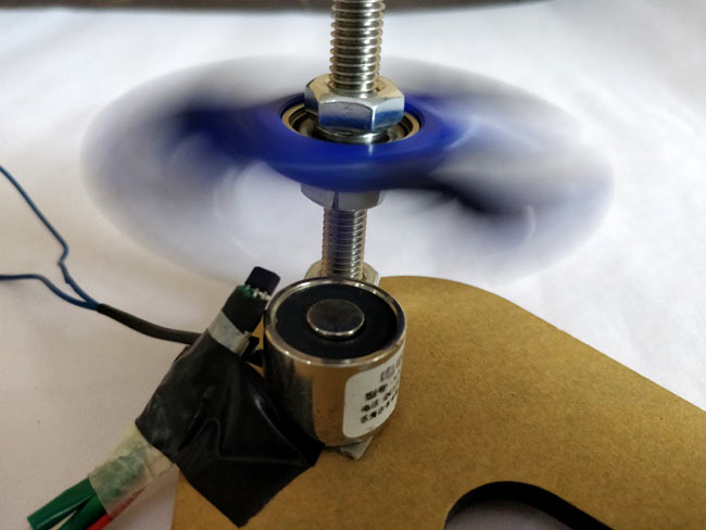
Once you are done with your circuit place hall sensor a little above the electromagnet and then place your fidget spinner over the electromagnet maintaining a minimum air gap. I have used a threaded bolt and nut to make the required arrangement you can use your own method. Mine looks something like this below.

Let’s Spin The Fidget Spinner:
Once you are ready with the circuit and have arranged the spinner as shown above its time to see your fidget spinner as BLCD Motor. Just give the spinner an initial push and you will have it rotating forever as shown in the video below.
If it does not work as expected use the LED in the circuit to check if the hall sensor is working and also check if the Electromagnet is energised and de-energised properly. Also make sure the right side of the hall sensor is faced up and the magnets are also of the same polarity as described earlier. The speed of the spinner depends on the position of the hall sensor and the distance of air gap. You can experiment with the hall sensor and check at which position you are getting maximum speed.
Hope you understood the project and enjoyed building something similar. If you have any problem in getting this work use the comment section to post your problem or use the forum for more technical help. Stay creative and we will meet in next project, until then happy spinning.
Comments
The circuit diagram is
The circuit diagram is already given above
bro nice simple project......
bro nice simple project.......keep go ahead
Comment on fidget spinner motor
Hassan, your project is very well documented and the explanations of each parts well explained. Congratulation.
I had a L293D lying around so
I had a L293D lying around so I used it. You can use any type of transistor to switch it

nice project can you send me the circuit of the project.