

“Eyes sense what mind sees.” Like this LDR (light dependent resistor) sense if there is any light source in its sensing range. It’s true that you can manually switch OFF and ON any light, but sometime human beings shows carelessness which may cause waste of electricity. To overcome this problem, we are going to show you that how to make a Light Detector Circuit (which helps in sensing the light) and you can add a relay to operate the AC Home appliances depend on the sensation of light. Although we have previously created some Light Detector Circuit but this time we are using Wheatstone Bridge concept to operate the LDR.
Check our other circuits which use LDR for light detection:
- Dark Detector using LDR and 555 Timer IC
- Raspberry Pi Emergency Light with Darkness and AC Power Line Off Detector
- Dark and Light Indicator Circuit
- Automatic Staircase Light
- Automatic Street Light
- Laser Security Alarm Circuit
Required Components
- LDR
- Transistor (BC547)
- LM741op-amp IC
- Potentiometer (10k)
- Resistance (10k, 330ohm)
- Led (red)
- Battery (9v)
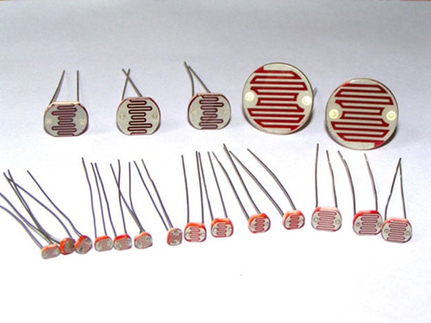
LDR (Light Dependent Resistor)
LDR is type of resistor whose resistance vary with the strength of light fall over it. It’s made up of a semiconductor name Cadmium sulphide. When it’s dark the resistance of LDR is in mega or kilo ohms and as the light falls, it changes it resistance from mega ohms to few hundreds ohms. It simply means that the presence of light decreases the resistance of LDR and that is how it is used to predict day and night.
Working of LDR
The LDR works on the principle of photo conductivity, when the light falls on the surface of LDR then the resistance of LDR start decreasing from a high value of it, in the dark resistance of LDR is in range of Mega ohms and as the light incident on it resistance decreases to a range of few ohms. The electrons in the valence band jumps to conduction band, due to having high energy of photons in the incident light then the semiconductor material.
Features
- Cell resistance is 400ohms to 9 kilo ohms, when lux of 1000 to 10 is provided.
- In dark the resistance is minimum one mega ohm.
- Having 2.8 to 18ms of rise time and 48 to 120ms of fall time.
- Having wide range of spectral response
- Economical in cost
- High ambient temperature range
Applications
- Automatic Street Light
- Position sensor
- Light intensity meters
- Burglar alarm circuits
- Used along with LED as obstacle detector
- Automatic bedroom Lights
Op amp IC LM741
An operational amplifier is a DC-coupled high gain electronic voltage amplifier. It’s a small chip having 8 pins. An operational amplifier IC is used as a comparator which compares the two signal, the inverting and non-inverting signal. In Op-amp IC 741 PIN2 is an inverting input terminal and PIN3 is non-inverting input terminal. The output pin of this IC is PIN6. The main function of this IC is to do mathematical operation in various circuits.
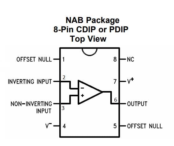
Op-amp basically has Voltage Comparator inside, which has two inputs, one is inverting input and second is non-inverting input. When voltage at non-inverting input (+) is higher than the voltage at inverting input (-), then the output of comparator is HIGH. And if the voltage of inverting input (-) is Higher than non-inverting end (+), then output is LOW.
In our light detector circuit, the op-amp IC comparing the voltage of the point C and D through the PIN3 and PIN2 respectively, as we know if the voltage at PIN3 is more than PIN2 the output at PIN6 will be HIGH and vice versa. As the output HIGHs the Led will start glowing. For getting the HIGH output we must have to incident light on LDR to reduce its resistance which increase the voltage at point C.
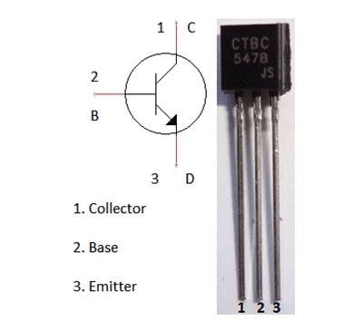
Transistor (BC547)
It’s a NPN transistor, the amplification capacity is also good as having a gain value of 110 to 800. It allows 100mA of maximum current flow through the collector pin and input current limit is 5mA to the base pin for biasing. As the base pin kept ground the transistor moves to reverse biased condition and do not conduct current through it (which is the Cut-Off point), as supply provide to base pin it start conducting through the emitter to collector (which is the Saturating point). The normal voltage range through the collector-emitter and base-emitter is 200 and 900mV respectively.
In our circuit, the transistor is work as a switch for the LED. As the output of the op-amp high (means light is pointing on LDR) which is then fed to the base of the transistor then current through the collector to emitter start flowing. When the output of op-amp is low (means its dark), the transistor remains in off condition no current flows through collector to emitter till the output goes highs.
|
Pin Number |
Pin Name |
Description |
|
1 |
Collector |
Current flows in through collector |
|
2 |
Base |
Controls the biasing of transistor |
|
3 |
Emitter |
Current Drains out through emitter |
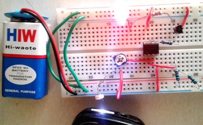
Circuit Diagram of Light Detector:


Working of Light Detector using Wheatstone bridge
As we know in Wheatstone bridge, if the difference of voltage drop is zero between point C and D the ratio of resistance R1 and R2 is equal to the ratio of resistance R3 and R4, where R4 is the unknown resistance, R1 and R2 are known resistors and R3 is the potentiometer.

Here in our Light detector circuit diagram, Wheatstone Bridge is consists of one LDR and potentiometer in the first arm and two known resistance of 10k ohm in the second arm. As the light incident on the LDR, it resistance gets low and the voltage through point C is increase in comparison with point D.
An Op-amp IC LM741 is used to compare the voltage of both the point C and D, if the voltage of point C is more than point D then the op-amp give high output and if point D has more voltage then one then op-amp give low output. As the op-amp output is high it turns on the transistor and the Led start glowing (which means the presence of light) and if low then op-amp output is low and transistor remains in off condition (which means its dark).

it is a good design.