

In this project we are going to make Clapper circuit using the concept of ADC (Analog to Digital Conversion) in ARDUINO UNO. We are going to use a MIC and Uno to sense the sound and trigger a response. This Clap ON Clap OFF switch basically turns ON or OFF the device, by using the clap sound, as switch. We have previously built Clap switch and Clap ON Clap OFF switch, using 555 Timer IC.
On clapping there will be a peak signal at the MIC which is much higher than normal, this signal is fed to the amplifier, though a High Pass Filter. This amplified voltage signal is fed to ADC, which converts this high voltage into a number. So there will be a peak in the ADC reading of the UNO. On this peak detection we will toggle an LED on the board, on each clap. This project has been explained in detail below.
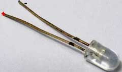
MIC or Microphone is a sound sensing transducer, which basically converts sound energy into electrical energy, so with this sensor we have sound as changing voltage. We usually record or sense sound through this device. This transducer is used in all mobile phones and laptops. A typical MIC looks like,
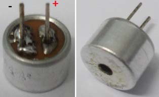
Determining the polarity of Condenser Mic:
MIC has two terminals one is positive and another is negative. Mic polarity can be found using a Multi-Meter. Take the positive probe of Multi-Meter (put the meter in DIODE TESTING mode) and connect it to one terminal of MIC and the negative probe to the other terminal of MIC. If you get the readings on the screen then the terminal of positive (MIC) is at negative terminal of Multi-Meter. Or you can simply find the terminals by looking at it, the negative terminal has two or three soldering lines, connected to the metal case of the mic. This connectivity, from negative terminal to its metal case can also be tested using continuity tester, to find out the negative terminal.
Components Required:
Hardware:
ARDUINO UNO, power supply (5v), a condenser mic (explained above)
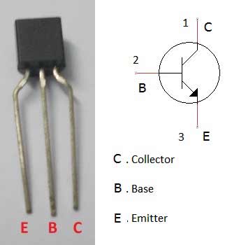
2N3904 NPN transistor,
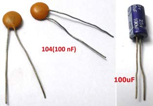
100nF capacitors (2 pieces), one 100uF capacitor,
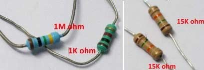
1K Ω resistor, 1MΩ resistor, 15KΩ resistor (2 pieces), one LED,
And Breadboard & Connecting wires.
Software: Arduino IDE - Arduino nightly.
Circuit Diagram and Working Explanation:
The circuit diagram of the clapper circuit is shown in below figure:

We have divided the working into four parts, that is: Filtration, Amplification, Analog-digital conversion and programming to toggle the LED
Whenever there is sound, the MIC picks it up and converts it into voltage, linear to the magnitude of sound. So for a higher sound we have higher value and for lower sound we have lower value. This value is first fed to the High Pass Filter for filtration. Then this filtered value is fed to the transistor for amplification and transistor provides the amplified output at the collector. This collector signal is fed to the ADC0 channel of the UNO, for Analog to Digital conversion. And lastly Arduino is programmed to toggle the LED, connected at PIN 7 of PORTD, each time ADC channel A0 goes beyond a particular level.
1. Filtration:
First of all we will talk briefly about R-C High Pass Filter, which has been used to filter out the noises. It’s easy to design and consists of a single resistor and single capacitor. For this circuit we don’t need much detail, so we will keep it simple. A high pass filter allows signals of high frequency pass from input to output, in other words the input signal appears at the output if the frequency of signal is higher than the filter prescribed frequency. For now, we need not to worry about these values because here we are not designing an audio amplifier. A high pass filter is shown in the circuit.
After this filter, voltage signal is fed to the transistor for amplification.
2. Amplification:
The voltage of MIC is very low and cannot be fed to UNO for ADC (Analog to Digital Conversion), so for this we design a simple amplifier using a transistor. Here we have designed a single transistor amplifier for amplifying the MIC voltages. This amplified voltage signal is further fed to the ADC0 channel of Arduino.
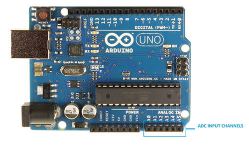
3. Analog to Digital Conversion:
ARDUINO has 6 ADC channels. Among those, any one or all of them can be used as inputs for analog voltage. The UNO ADC is of 10 bit resolution (so the integer values from (0-(2^10) 1023)).This means that it will map input voltages between 0 and 5 volts into integer values between 0 and 1023. So for every (5/1024= 4.9mV) per unit.
Now, for the UNO to convert analog signal into digital signal, we need to Use ADC Channel of ARDUINO UNO, with the help of below functions:
1.    analogRead(pin);
2.    analogReference();
UNO ADC channels have a default reference value of 5V. This means we can give a maximum input voltage of 5V for ADC conversion at any input channel. Since some sensors provide voltages from 0-2.5V, so with a 5V reference, we get lesser accuracy, so we have an instruction that enables us to change this reference value. So for changing the reference value we have “analogReference();”
In our circuit, we have left this reference voltage to the default, so we can read value from ADC channel 0, by directly calling function “analogRead(pin);”, here “pin” represents pin where we connected the analog signal, in this case it would be “A0”. The value from ADC can be taken into an integer as “int sensorValue = analogRead(A0); ”, by this instruction the value from ADC gets stored in the integer “sensorValue”. Now, we have the transistor value in digital form, in the memory of UNO.
4. Program Arduino to Toggle the LED on each Clap:
Under normal instances, the MIC provides normal signals and so we have normal digital values in the UNO, but on clapping there a peak provided by the MIC, with this we have a peak digital value in the UNO, we can program the UNO to toggle an LED ON and OFF whenever there is a peak. So on first clap the LED turns ON and stays ON. On second clap the LED turns OFF and stays OFF until the next clap. With this we have the clapper circuit. Check the program Code below.
Complete Project Code
const int analogInPin = A0;  // Analog input pin 0

int sensorValue = 0;

void setup()

{

 DDRD = 0xFF;

}
void loop()

{

 sensorValue = analogRead(analogInPin);    //read ADC value on channel 0

 if(sensorValue>60)

 {

  PORTD ^=(1<<7); //If there is a peak toggle the LED on and OFF on pin7.

  delay(250);

  }

}
Comments
It is connected across the 5v
It is connected across the 5v power and Ground from Arduino to the Breadboard. Check the project image at the top.
Help Please
Hi
I hope you can help me, I'm not good with electronics but I'm looking for a circuit that can take low frequency sound ( like the sound of a bass speaker) and switch a 12v motor so that it can move on the sound of the base speaker.
I think your circuit is the one except it is for high frequencies.
Is there something like that that I can buy ?
please help me
What kind of motor you want
What kind of motor you want to rotate? We have some music operated circuits please check: Music Operated Dancing LEDs, if you want to rotate simple DC motor just connect it in place of LED
i was wondering how you got
i was wondering how you got to those values of the resistors and capacitors can you show the calculations used
Check this for calculations:
Check this for calculations: Music Operated Dancing LEDs,
Why the 1M resistor is not
Why the 1M resistor is not connected to ground?
in the 9th line of the code.
in the 9th line of the code. i thing is wrong.
my software is ardino 1.6.8
so it show [analogInPin] was not declared in this scope.
pls tell me what can i do sir
Just replace "analogInPin"
Just replace "analogInPin" with "A0", it will work
hi what do these mean? DDRD
hi what do these mean? DDRD = 0xFF; , PORTD ^=(1<<7);
programing of circuit
can uu send the programing for this circuit. i want to use for my final project
Code is already given above
Code is already given above in Code section, please check carefully.
Analog signal LED flasher/solid
Hello;
I am new in this field i need a simple single LED flasher/Solid circuit that accepts 3 types of input signal from a circuit one is positive +5v to gnd and other is -5v to gnd when +5 signal input to arduino it should solid ON and when -5v signal input the LED starts flashing LED at rate of 2sec and when no signal (below 2v) LED off.
just curious
Hi There,
Great write up and coding. Its awesome. A few questions pending my objective: For some reason I decided to make a clapper and do all the work necessary to actually make it work. You can buy them for cheap but hey, why not. Great learning opportunity. I have made a clapper that works semi sort of and I use code that doesn't analyze frequency but rather amplitude. I can't decipher the difference between a loud stomp vs a clap at this time... I would like to implement frequency into it but haven't gone that far, additionally, there are no filters in my circuit. Feedback comes straight from the mic, I give it a gain and Arduino reads it and spits out an Analog value. It appears yours does to with some high pass filters implemented. My questions:
Why use a high pass filter mechanically vs programmaticly? Can programming filter it the same without additional delay?
With your code, can you tell the difference between a high amplitude door slamming vs a clap (for example)?
Thanks for your feedback!
Cheers,
Tim
High pass filter is added for
High pass filter is added for better accuracy. When signal reaches to Arduino, it is Amplified and Digital converted, so it wont remain the original signal, so its better to filter the original signal instead of filtering the virtual signal pragmatically.
Clap switch code
Hi, i have chosen your design as project. I have designed this project and all works fine. However, i wanted to ask is it possible for you to design code for the clap switch to response to two claps between two seconds and if there is only one clap then the process resets. Please get back to me. Thank you once again for this amazing project. I hope to hear back from you.
Hey,
Hey,
Great project and works well.
But if you could help me out on one thing. I want to move a servo motor instead of glowing led. Like on the first clap the servo should go from 0 to 180 and second clap 180 to 0. If anyone could help me with the arduino code of it that would be really helpful as i dont know much about code and am a beginner. Thank you so much.
In above clap switch circuit,
In above clap switch circuit, I also want to join 5V small fan to turn on it using clap or any other thing, So how can i do this ?
Just connect the fan or any
Just connect the fan or any load in parallel with the LED and it will work

i am wondering where i should put the 100uF capacitor. where is it in the schematic?