
If Subwoofer in your music system is not producing enough bass then you can use this simple DIY circuit to enhance the Bass. In this project we are going to design a Subwoofer Amplifier Circuit Using IC TDA2030 with few cheap components. This TDA2030 Amplifier can produce 14watt output and this can be increased upto 30watt by using another TDA2030. Also check our previous Audio Amplifier circuits:
- LM386 Based Audio Amplifier Circuit
- Simple Audio Amplifier using 555 Timer IC
- Headphone/Audio Amplifier Circuit on PCB
Required Components:
- Audio jack pin – 1
- TDA2030 IC - 1
- Resistors – 100K (3), 4.7 K(1), 10 ohm (1)
- Capacitor – 100 mf (1), 0.1 mf (2), 2.2 mf (2) , 22mf(1)
- Diode – In4007 (1)
- Speaker (1)
- Battery – 12 V (I used SMPS)
- 22k variable resistor-1 (To adjust volume if needed)
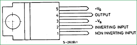
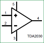
Features and Pin Detail of TDA2030 Amplifier:
TDA2030 can work with the range of voltage between 9 V to 24 V with total harmonic distortion of 0.08. It has the ability to deliver the output of 18 W. Below is the Top View and Pin Diagram of TDA2030 from its datasheet:
Circuit Diagram and its Working:

Above is the circuit Diagram for this TDA2030 based Amplifier Circuit. We have connected a 2.2uf capacitor in series to the non-inverting pin of the TDA2030, here it is acting as the High Pass Filter. So that it allows only the high frequency audio signal. There is a resistor (R4) between pin 2 and 4 we called that resistor as Feedback Resistor. This feedback resistor is used to obtain the gain. If the feedback resistor is improper then the subwoofer amplifier will not work properly.
In the circuit diagram, resistor (R1) and a capacitor (C2) are connected in series, with pin 2 of the TDA 2030 to suppress the noises in the audio signal. Pin 3 is grounded, means connected to negative terminal of power supply. The output of the TDA2030 is connected with the series capacitor of the value 2200uf to allow amplified signal to the speaker. The pin 5 is having a resistor of 100k which functioned as the voltage divider biasing. This sub-woofer circuit has the capacity to deliver 12 W output. We can we can use speaker of 4 to 6 ohm speaker. It will be better if we use a heat sink to remove the high temperature in the TDA 2030. If necessary you can also add a cooling fan for the better working.
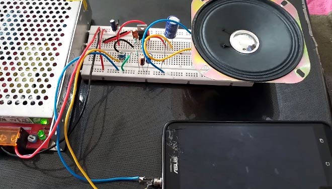
For the volume adjustment we are using 22 kilo ohm variable resistor. Connect the audio signal wire to the any one end of the variable resistor and connect the center pin to the input signal C1 of the capacitor. And connect the ground to the other end of the variable resistor. By changing the variable resistor we can change the volume of the subwoofer of td2030. IN4007 diode is used to avoid interchange of polarity of IC to avoid from burning and two capacitors C7 and C6 are used to eliminate the noises present in the power supply. The resistor R6 and C5 are also helps to avoid the unwanted the noises in the speaker (Blur sounds). I used 12v smps as power supply to power the entire circuit.
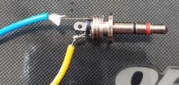
For Connecting the 3.5mm Audio jack, Solder one wire to the stereo jack ground pin and one wire to either left or right pin. In below picture blue wire is ground and yellow wire is audio signal. Then connect the audio jack to mobile or laptop to enjoy music.
So this is how, we can easily build the Subwoofer amplifier circuit using TDA2030. Below is the Demonstration Video for this amplifier circuit.
Comments
usb,sd card mp3 player
is it possible to make USB,SD
CARD MP3 player at home, which IC can I use
I made it but the sound is
I made it but the sound is very very low. please anyone give the solution of this problem.
What power source are you
What power source are you using? make sure i can provide enough current

good performance in electronic project , Never give up!!!