
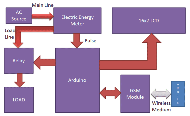
Prepaid Electricity Energy Meter is a good concept in which you can recharge its balance, like we do in our mobile phones. In this project we are building a automated system by using Arduino and GSM module. You can recharge the electricity balance through this system, just by sending a SMS. It can also disconnect the home power supply connection, if there is low or zero balance in the system. And this system will reads the energy meter readings and automatically send some updates to user’s mobile phone like low balance alert, cut off alert, resume alert and recharge alert.
Working explanation:
Here we have interfaced electricity energy meter with Arduino using the pulse LED (Calibration or Cal) of electricity Energy meter. We only need to connect tis CAL LED to Arduino through an Optocoupler IC.
Components used:
- Arduino
- GSM Module
- 16x2 LCD
- Analogue Electricity Energy Meter
- Optocoupler 4n35
- Resistors
- POT
- Connecting wires
- Bulb and holder
- SIM card
- Power supply
- Mobile Phone
When we power up the system then it reads previous values of rupees stored in EEPROM and restores them into the variables then checks the available balance with the predefined value and take action according to them, like if available balance is greater than 15 rupees then Arduino turns On the electricity of home or office by using relay. And if balance is less than 15 rupees then Arduino sends a SMS to user phone regarding low balance alert and requesting to recharge soon. And if balance is less than 5 rupees then Arudino turns Off the electricity connection of home and sends a SMS to user’s phone for ‘Light Cut’ alert and requesting to recharge soon. GSM module has been used to send and receive messages, you can check about GSM module and AT commands here.
Now when we need to recharge our system, we can recharge it simply by sending a SMS to the system, through our Cellphone. Like if we want to recharge by 45 bucks then we will send #45*, here # and * are prefix and suffix to the recharge amount. System receives this message and extract recharge amount and update the balance of system. And system again turns On the electricity of the house or office. This flow of working can be understood through the video at the end.
Circuit Description:
Circuit connections for this Wireless Electricity Meter Reading Project, are shown in the diagram; we have used a Arduino UNO for processing all the things used in project. A liquid crystal display is used for displaying the status of Units and remaining balance. Data pins of LCD namely RS, EN, D4, D5, D6, D7 are connected to Arduino digital pin number 7, 6, 5, 4, 3, 2. And Rx and Tx pins of GSM module are directly connected to the Tx and Rx pins of Arduino respectively. And GSM module is powered by using a 12 volt adaptor. A relay is used for switching electricity connection which is connected at pin 12 of Arduino though ULN2003 relay driver.

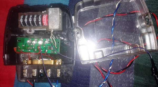
How to Connect Energy Meter with Arduino:
First user need to buy an Analogue Electricity Energy Meter. After it user needs to open it and find the Pulse LED or Cal LED’s terminals (cathode and Anode). Now solder two wires at both the terminals and take it out from the energy meter and then close energy meter and tight the screws.
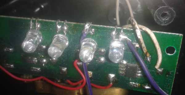
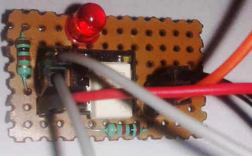
Now user needs to connect anode terminal of LED at pin number 1 of Optocoupler and cathode terminal to pin 2. Pin number four of optocouper should be directly connected to ground. A LED and a Pull-up resistor are connected at pin number 5 of optocoupler. And same terminal should go to the Arduino pin 8 too.
Calculation of Pulses and Units:
Before proceeding for the calculations, first we have to keep in mind the pulse rate of energy meter. There are two pulse rates of energy meter first is 1600 imp/kwh and second is 3200 imp/kwh. So here we are using 3200 imp/kwh pulse rate energy meter.
So first we need to calculate the Pulses for 100watt, means how many times Pulse LED will blink in a minute, for the load of 100 watts.
Pulse= (Pluse_rate*watt*time)/ (1000*3600)
So pulses for 100 watt bulb in 60 seconds, with energy meter of 3200 imp/kwh pulse rate can be calculated as below:
Pulses=3200*100*60/1000*3600
Pulses = ~5.33 pulse per minute
Now we need to calculate Power factor of a single pulse, means how much electricity will be consumed in one pulse:
PF= watt/(hour*Pulse)
PF=100/60*5.33
PF=0.3125 watt in a single pulse
Units= PF*Total pulse/1000
Total pulses in an hour is around 5.33*60=320
Units = 0.3125*320/1000
Units = 0.1 per hour
If a 100 watt bulb is lighting for a day then it will consume
Units =0.1*24
Units = 2.4 Units
And suppose unit rate is at your region is 5 rupees per unit then
You have to pay for 2.4 Units Rs:
Rupees= 2.4*5 = 12 rupees
Programing explanation:
First of all we include required library and Define pins & variables that are required in our project. This can be seen in first few lines of our program code below.
After it we initialize the LCD, serial communication, GSM and display some message message.
After this in loop function we read serial received data if any. And reads pulse from energy meter and show units and balance on LCD.
void setup()
{
  lcd.begin(16,2);
  Serial.begin(9600);
  pinMode(led, OUTPUT);
  .. ...
  ... ....
lcd.print("Circuit Digest");
  lcd.setCursor(0,1);
  delay(2000);
  lcd.print("GSM Initilizing...");
  gsm_init();
  .. ...
  ... ....
After this in loop function we read serial received data if any. And reads pulse from energy meter and show units and balance on LCD.
void loop()
{
  serialEvent();
  rupees=EEPROM.read(1);
  units=rupees/5.0;
  lcd.setCursor(0,0);
  lcd.print("Units:");
  .. ...
  ... ....
void init_sms(),void send_data(String message), and void send_sms() functions have been used to send SMS.
gsm_init() function is used for initializing the GSM module for get ready to operate with the system. In this we first sends AT command to know whether GSM module is connected or not. After it we turned off the echo and then check the network.
void gsm_init()
{
  lcd.clear();
  lcd.print("Finding Module..");
  boolean at_flag=1;
  while(at_flag)
  .. ...
  ... ...
In check_status() function system reads connection and Balance conditions; like whether electricity balance is greater than the defined limit. If balance is less than 15 , then it alerts the user by sending the SMS alert of ‘Low Balance’ and if balance is less than 5 rupees then system will cut the electricity and inform the user by sending SMS using GSM module.
void check_status()
{
  if(rupees>15)
   {
    digitalWrite(relay, HIGH);
    flag1=0;
    .. ...
    ... ....
send_confirmaiton_sms() function is used for sending confirmation message to the user if recharge has been done and it also update the balance in the system.
decode_message() function is used for decoding the amount figure from the SMS message, by using the # and * as starting and ending character.
read_pulse() function is used for reading pulse from the Energy meter through optocoupler IC. And update the unit and balance.
void read_pulse()
{
  if(!digitalRead(pulsein))
   {
    digitalWrite(led, HIGH);
    if(units<1){}
    .. ...
    ... ....
serialEvent() function is used for serial communication and receiving the message.
Complete Project Code
#include<EEPROM.h>
#include <LiquidCrystal.h>
LiquidCrystal lcd(7,6,5,4,3,2);
int led=13;
#define pulsein 8
#define relay 12
unsigned int pusle_count=0;
float units=0;
unsigned int rupees=0;
 float watt_factor=0.3125;
unsigned int temp=0,i=0,x=0,k=0;
char str[70],flag1=0,flag2=0;
String bal="";
void setup()
{
  lcd.begin(16,2);
  Serial.begin(9600);
  pinMode(led, OUTPUT);
  pinMode(pulsein, INPUT);
  pinMode(relay, OUTPUT);
  digitalWrite(pulsein, HIGH);
  lcd.setCursor(0,0);
  lcd.print("Automatic Energy");
  lcd.setCursor(0,1);
  lcd.print("      Meter    ");
  delay(2000);
  lcd.clear();
  lcd.print("Circuit Digest");
  delay(2000);
  lcd.clear();
  lcd.print("GSM Initilizing...");
  gsm_init();
  lcd.clear();
  lcd.print("System Ready");
  Serial.println("AT+CNMI=2,2,0,0,0");
  init_sms();
  send_data("System Ready");
  send_sms();
  delay(1000);
  digitalWrite(led, LOW);
  lcd.clear();
//  EEPROM.write(1,0);
 // rupees=EEPROM.read(1);
}
void loop()
{
    serialEvent();
    rupees=EEPROM.read(1);
    units=rupees/5.0;
    lcd.setCursor(0,0);
    lcd.print("Units:");
    lcd.print(units);
    lcd.print("      ");
    lcd.setCursor(0,1);
    if(rupees<15)
    lcd.print("LOW Balance:");
    else
    lcd.print("Balance:");
    lcd.print(rupees);
    lcd.print("      ");
    read_pulse();
    check_status();
    if(temp==1)
    {
     decode_message();
     send_confirmation_sms();
    }
}
void serialEvent()
{
  while(Serial.available())
  {
    char ch=(char)Serial.read();
    str[i++]=ch;
    if(ch == '*')
    {
      temp=1;
      lcd.clear();
      lcd.print("Message Received");
      delay(500);
      break;
    }
  }
}
void init_sms()
{
   Serial.println("AT+CMGF=1");
   delay(200);
   Serial.println("AT+CMGS=\"+918287114222\"");
   delay(200);
}
void send_data(String message)
{
  Serial.println(message);
  delay(200);
}
void send_sms()
{
  Serial.write(26);
}
void read_pulse()
{
    if(!digitalRead(pulsein))
    {
      digitalWrite(led, HIGH);
      //count++;
      //units=watt_factor*count/1000;
      if(units<1){}
      else
      units--;
      rupees=units*5;
      EEPROM.write(1,rupees);
      while(!digitalRead(pulsein));
      digitalWrite(led,LOW);
     // delay(2000);
    }
}
void check_status()
{
      if(rupees>15)
      {
        digitalWrite(relay, HIGH);
        flag1=0;
        flag2=0;
      }
      if(rupees<15 && flag1==0)
      {
       lcd.setCursor(0,1);
       lcd.print("LOW Balance       ");
       init_sms();
       send_data("Energy Meter Balance Alert:");
       send_data("Low Balance\n");
       Serial.println(rupees);
       delay(200);
       send_data("Please recharge your energy meter soon.\n Thank you");
       send_sms();
       message_sent();
       flag1=1;
      }
      if(rupees<5 && flag2==0)
     {
      digitalWrite(relay, LOW);
      lcd.clear();
      lcd.print("Light Cut Due to");
      lcd.setCursor(0,1);
      lcd.print("Low Balance");
      delay(2000);
      lcd.clear();
      lcd.print("Please Recharge ");
      lcd.setCursor(0,1);
      lcd.print("UR Energy Meter ");
      init_sms();
      send_data("Energy Meter Balance Alert:\nLight cut due to low Balance\nPlease recharge your energy meter soon.\n Thank you");
      send_sms();
      message_sent();
      flag2=1;
    }
}
void decode_message()
{
  x=0,k=0,temp=0;
     while(x<i)
     {
      while(str[x]=='#')
      {
        x++;
        bal="";
        while(str[x]!='*')
        {
          bal+=str[x++];
        }
      }
      x++;
    }
    bal+='\0';
}
void send_confirmation_sms()
{
    int recharge_amount=bal.toInt();
    rupees+=recharge_amount;
    EEPROM.write(1, rupees);
    lcd.clear();
    lcd.print("Energy Meter ");
    lcd.setCursor(0,1);
    lcd.print("Recharged:");
    lcd.print(recharge_amount);
    init_sms();
    send_data("Energy Meter Balance Alert:\nYour energy meter has been recharged Rs:");
    send_data(bal);
    send_data("Total Balance:");
    Serial.println(rupees);
    delay(200);
    send_data("Eelctricity Has Been Connected\nThank you");
    send_sms();
    temp=0;
    i=0;
    x=0;
    k=0;
    delay(1000);
    message_sent();
}

void message_sent()
{
  lcd.clear();
  lcd.print("Message Sent.");
  delay(1000);
}
void gsm_init()
{
  lcd.clear();
  lcd.print("Finding Module..");
  boolean at_flag=1;
  while(at_flag)
  {
    Serial.println("AT");
    while(Serial.available()>0)
    {
      if(Serial.find("OK"))
      at_flag=0;
    }
    delay(1000);
  }
  lcd.clear();
  lcd.print("Module Connected..");
  delay(1000);
  lcd.clear();
  lcd.print("Disabling ECHO");
  boolean echo_flag=1;
  while(echo_flag)
  {
    Serial.println("ATE0");
    while(Serial.available()>0)
    {
      if(Serial.find("OK"))
      echo_flag=0;
    }
    delay(1000);
  }
  lcd.clear();
  lcd.print("Echo OFF");
  delay(1000);
  lcd.clear();
  lcd.print("Finding Network..");
  boolean net_flag=1;
  while(net_flag)
  {
    Serial.println("AT+CPIN?");
    while(Serial.available()>0)
    {
      if(Serial.find("+CPIN: READY"))
      net_flag=0;
    }
    delay(1000);
  }
  lcd.clear();
  lcd.print("Network Found..");
  delay(1000);
  lcd.clear();
}
Comments
Hello. Do you have software simulation of this project on Proteus ISIS? I am also making this project but I also want to simulate this project on Proteus ISIS. Thanks.
Dear Concern,
it's working but unite or amount is reduced with every pulse.So if i pay 25 rupees unite will be 5 so after one pulse balance reduce 5 rupees .so please help me.
Thanking You
hello sir ...
please if your program you used but a fixed load of 100w which impact on the number of pulses per minutes what if we wish to use but a variable load size maybe like many bulbs ....??
i want to this project in bangladeshi tk that means in bangladesh,,,so what should be done/change instead of rupee in code?
please sir how did you generate pumse of the meter in proteus during the simulation??
i want to buy all the components used in this project. How much costlier it would be??
can i ask? if im using digital meter where the port that i used to connect to arduino? at port of pulse ouptut passive?
DEAR CONCERN,
THIS IS NICE PROJECT AND IT APPLICATION IS NEW IN OUR GENERATION.WE WANT TO DO THIS PROJECT IN OUR FINAL YEAR.
CAN YOU HELP US BY GIVING THE CIRCUIT DIAGRAM AS WELL AS PROGRAMMING CODE,SIMULATION DIAGRAM.
IT WILL BE VERY HELPFUL FOR US.
Sir I done this project as per the diagram but a high voltage is getting from pulse that I connected to optocoupler. then I get shock from the arduino please give a solution
sir, could u please tell me how did you make that energymeter device in proteus simulation.
Proteus has drawing tools. you can use it to create custom devices. But, they can only be used as representation they cannot be simulated unless you design it
Very nice project
thanks for your good project.
WE WANT TO DO THIS PROJECT
CAN YOU HELP US BY GIVING THE CIRCUIT DIAGRAM AS WELL AS PROGRAMMING CODE
we are doing electrical engineering we are not good in programming thxs sir
Sir, the project which you have done is awesome but you have tested the reading with one load,my question is that ,if I want to have readings of multiple loads at a time.,then what I have to do?
how to implement the energy meter in proteus please reply me with the procedure
ENERGY METER USED IN CIRCUIT DIAGRAM CANN'T FOUND IN PROTEUS WHER YOU GET THIS COMPNENT .....?
We are doing the same project so please send the clear circuit diagram and program code
Can you give me the simulation of this project
Hii I am doing this project, I wanted the programming code of this project which deducts the mobile balance.
And I am using arduino relay 2 channel and removed the relay driver is that ok -?
And most important how to take pulse ?
Plzz help
hello ,nice project...can u please provide the code and detail working of circuit.
we have assembled the circuit , but it's not work properly .it displayed "Finding module" messege.
Hello sir,
Is it possible to have digitalread from negative terminal of the led as you did in this project?
usually we used to have digitalread from positive terminal...
By doing your way we cant able to read the cal led.so that the units are not increasing.
get confuse on operation how recharge amount deduce and how can we recharge
hello sir
i have made this circuit but little bit confused about the connection of relay module (INT pin)
where it should be connected?
please replay me fast as possible
This project is good but it's not working
I have digital meter but units is not showing in LCD display
Dear Sir/Madam,
I have compiled your code and downloaded it on UNO board. Initially the code worked fine. However, later on the balance on LCD shows 0 while I have balance on my sim. In case if the balance is zero, the program should execute the further instructions indication user the balance is low through sms, which is also not working. Kindly provide the necessary help in this regards.
circuit connected successfully but it is stuck at FINDING MODULE ,,,... please help....
sir, whole circuit is connected properlly, but relay can not operate.
due to this bulb can not start and balance of lcd displace can not change.
ans also red led which is connected to optocoupler is not turn on.
please help me.
Sir, where did u get the energy meter component for Proteus simulation circuit?
i am Irfan ullah student of b.tech electrical last semester my final year project is Bidirectional energy meter ..so kindly help me how to perform it and how to star it...
This is my project sir please anyone explain and sends its thesis....
I am doing smart energy meter project but I am not getting output because after completing whole connections and executing arduino is getting damaged everytime.can anyone resolve my problem? Please it's very urgent guys.
What do you mean by arduino is getting damaged. Check your connections, mainly your power supplies. You must be creating a short some where
Why we divide by 1000 to get the units per hour ??
The entire circuit works as expected except the SIM900. Texts are not sent or received. Is there any reason and has this been fixed?
Thanks!
while uploading the program on board there is a warning comes saying as below
Arduino: 1.8.5 (Windows 8), Board: "Arduino/Genuino Uno"
C:\Users\AMEY_9_96\Documents\Arduino\mm\mm.ino: In function 'void gsm_init()':
C:\Users\AMEY_9_96\Documents\Arduino\mm\mm.ino:218:26: warning: deprecated conversion from string constant to 'char*' [-Wwrite-strings]
if(Serial.find("OK"))
^
C:\Users\AMEY_9_96\Documents\Arduino\mm\mm.ino:234:26: warning: deprecated conversion from string constant to 'char*' [-Wwrite-strings]
if(Serial.find("OK"))
^
C:\Users\AMEY_9_96\Documents\Arduino\mm\mm.ino:250:36: warning: deprecated conversion from string constant to 'char*' [-Wwrite-strings]
if(Serial.find("+CPIN: READY"))
How to rectify this error???? Please reply as soon as possible
How many channels are used for relay in prepaid electricity billing meter project and what is use of optocoupler and pot in the project and resistor values ....any
Kjsensors are used in these project .please reply quickly sir
optocoupler is used for light sensing phenomeno. you can use it for light sensing
Guys if anyone has implemented it kindly help me I am trying but could not reached on result
Can you send me the orginal code
Sir, this type of error occurs, while I have compiled the code...due to that the simulation stuck at "Disabling ECHO'...
How to solve this error...
C:\Users\CHAUHAN\Documents\Arduino\sketch_oct04a\sketch_oct04a.ino: In function 'void gsm_init()':
C:\Users\CHAUHAN\Documents\Arduino\sketch_oct04a\sketch_oct04a.ino:232:26: warning: ISO C++ forbids converting a string constant to 'char*' [-Wwrite-strings]
if(Serial.find("OK"))
^
C:\Users\CHAUHAN\Documents\Arduino\sketch_oct04a\sketch_oct04a.ino:249:26: warning: ISO C++ forbids converting a string constant to 'char*' [-Wwrite-strings]
if(Serial.find("OK"))
^
C:\Users\CHAUHAN\Documents\Arduino\sketch_oct04a\sketch_oct04a.ino:266:36: warning: ISO C++ forbids converting a string constant to 'char*' [-Wwrite-strings]
if(Serial.find("+CPIN: READY"))
Can u plz help me to solve it.
C:\Users\Ujju\Desktop\mainprogram\mainprogram.ino: In function 'void gsm_init()':
C:\Users\Ujju\Desktop\mainprogram\mainprogram.ino:233:26: warning: deprecated conversion from string constant to 'char*' [-Wwrite-strings]
if(Serial.find("OK"))
^
C:\Users\Ujju\Desktop\mainprogram\mainprogram.ino:250:26: warning: deprecated conversion from string constant to 'char*' [-Wwrite-strings]
if(Serial.find("OK"))
^
C:\Users\Ujju\Desktop\mainprogram\mainprogram.ino:267:36: warning: deprecated conversion from string constant to 'char*' [-Wwrite-strings]
if(Serial.find("+CPIN: READY"))
^
Hello sir i'm going to perform this project for this semester
would you mind to provide me with the detail of the project?
how to count pulse and send me code
AOA...
Sir your idea is intresting one and i am douing this project as my final year project.Kindly tell me the name of the software on which you perform the above simulation.
hi guys someone please we tried this as our project and it is stuck at "Finding Module". any one have an idea on how to fix this>?? thanks
I am facing error in programing of arduino.
C:\Users\Ujju\Desktop\mainprogram\mainprogram.ino: In function 'void gsm_init()':
C:\Users\Ujju\Desktop\mainprogram\mainprogram.ino:233:26: warning: deprecated conversion from string constant to 'char*' [-Wwrite-strings]
if(Serial.find("OK"))
^
C:\Users\Ujju\Desktop\mainprogram\mainprogram.ino:250:26: warning: deprecated conversion from string constant to 'char*' [-Wwrite-strings]
if(Serial.find("OK"))
^
C:\Users\Ujju\Desktop\mainprogram\mainprogram.ino:267:36: warning: deprecated conversion from string constant to 'char*' [-Wwrite-strings]
if(Serial.find("+CPIN: READY"))
^
Can u plz help me as soon as possible.
not enough information, paste the complete error report from console
In the component list i dont get what the POT is. Please help
Hello can you share the proper stimulation in proteus of this project please thank you
it is good project, i do the this project how can we get the energy meter in protues liberary
did you get solution of your problem? if yes may you help me, i have the same problem.
sir how can get the full prposal
Thanks sir this materials are helpful, i would like to know how you included energy meter in proteus.
I would like to please someone for exactky describe for me which kind of components I need to use in this project.

Yes, the code and the circuit diagram will work as mentioned in the description. You can proceed.