

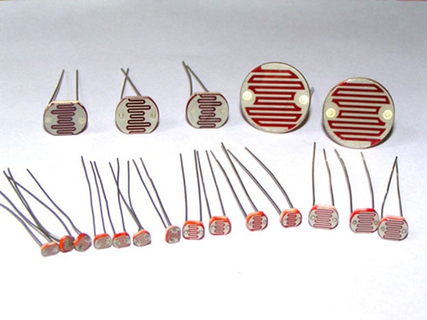
Darkness detector is simply a LDR (Light Dependent Resistor) interfaced square wave generator. In this project the square wave generator is developed as a 555 Timer IC based ASTABLE MULTIVIBRATOR. As this circuit is primarily based on the working principle of LDR, before going any further to understand this LDR circuit, we must get the basic details of the LDR. The figure below shows an image of various types of LDR.
What is LDR?
LDRs are made from semiconductor materials to enable them to have their light sensitive properties. There are many types but one material is popular and it is cadmium sulphide (CdS). These LDRs or PHOTO REISTORS works on the principle of “Photo Conductivity”. Now what this principle says is , whenever light falls on the surface of the LDR (in this case) the conductance of the element increases or in other words the resistance of the LDR falls when the light falls on the surface of the LDR. This property of the decrease in resistance for the LDR is achieved because it is a property of semiconductor material used on the surface.
Here in this dark detector circuit, LDR is configured with 555 ASTABLE in such a way that 555 ASTABLE generates square wave when the light intensity goes below a certain level.
Circuit Components
- +5 to +10 supply voltage
- 555 IC
- 100KΩ resistor
- 22KΩ resistor
- 10KΩ resistor
- 1MΩ pot or variable resistor
- 104(100nF) capacitor
- 2N3906 transistor
- LDR(any size)
- Speaker (25Ω,0.5WATT) or any other speaker.
Circuit Diagram

Above figure shows the circuit diagram of dark detector alarm. After some observation the circuit should seem very similar to the ASTABLE MULTIVIBRATOR, that is because the circuit is a ASTABLE MULTIVIBRATOR with only one modification. This modification is done at RESET pin (PIN4). In a normal ASTABLE vibrator this pin is connected to +5V, but since in this case we are supposed to generate pulse on the condition of absence of light it is not connected directly to +5v. The resistor network provided at the RESET pin provides a virtual ground so to keep resetting the IC and so the square wave output is stopped in the presence of light.
The transistor here drives the speaker because the speaker driven by IC is not a good idea. The speaker here can be replaced with LEDs to create an output response of lighting. So once the LEDs are placed and the darkness falls we will have an emergency backup light.
The transistor here need not be a PNP compulsory but one can replace it with a NPN and the pin connections should be connected accordingly.
Working
Before going to explanation, the circuit should be assumed ON and is not buzzing in the presence of light. This condition of non-buzzing in the presence of light can be achieved by adjusting the 1MΩ trim pot. Now in the circuit one can observe a voltage divider with 1M, 100K on one side and LDR on the other, the reset pin is connected in the middle. The trimmer pot is said to be adjusted because to create enough resistance on the top branch of voltage divider to drop almost all the potential (+5v) in the top branch itself. This leaves a virtual ground at the middle of divider (reset pin). Since the RESET pin of 555 is a LOW LEVEL triggered, the timer IC will be reset mode continuously and so there will be no square wave output as it should be. From this we can conclude that in the presence of light the 555 IC will be in complete reset and provides no output.
Now when the darkness falls on the LDR, the resistance of the LDR increases drastically as explained in introduction, this increase of resistance in the second branch (one with LDR) of voltage divider will be enough to change the ratio of voltage sharing between the two branches of voltage divider section. Once this happen, the potential at the junction of voltage divider circuit rises from 0V to 2V (approximately). And similarly the voltage at the RESET pin rises. This rise of voltage will be enough to lift the 555IC from reset mode. Once this reset mode is lifted, the timer generates square wave output. So it is concluded that once the darkness falls on the LDR the square wave output is generated by the timer.
The square wave generated by the timer is fed to the PNP transistor to drive the speaker. So the speaker outputs sound in response to the square wave.
Common Errors
Even after adjusting the trim pot the buzzing do not stop.
- The LDR might have enough resistance to put a potential at the reset pin. Put another 100KΩ resistor in series with 1MΩ pot.
- Check if the RESET pin (PIN4) is accidentally connected to +5V rail in any way.
There is no buzzing even in the dark.
- LDR might not be developing enough potential at the reset pin. Put a pot in series with LDR and adjust it to get buzzing.
The transistor is getting hot.
- Drive the signal of 555 troughs the 100Ω resistor to the base of transistor.
Comments
I suggest you to replace the
I suggest you to replace the Speaker with your 6v light and use NPN transistor (BC547) in place of PNP transistor.
needs help
Pls sir, how can I use this circuit with relay as the output?
connection problem
sir i don't know how to connect relay board with ldr sensor kit
send me the images and
Upload the images and circuit diagram(if you have) on forum. i will tell you.
I need help building the circuit... Plz
Hello sir, i need help with building the circuit, can u build more pics from different angles, with labels of each component, it would be a huge relief, and i'll be thankful...
inconsistency
There's so much inconsistency. Do you actually try out these circuits. Why don't you use a filter capacitor to connect the speaker to the suply? You have done that in other circuits.
Yes all the circuits are
Yes all the circuits are tested, you can check the given demo Video. You can also check Dark Detecting LED and Dark Detector using LDR and 555 Timer IC
the one I built detects the
the one I built detects the light only.
pls what's the solution

I'm trying to find out what I need to do to add a photocell (LDR) to a 6V DC battery powered strobe light. I assumed that I could just put it in line somewhere, but all my tests have proven that won't work. Any suggestions?