
RF Sensor and IR Sensor are very popular sensors, which are used to transmit and receive the data wirelessly and they have a wide range of applications. We have developed many projects using RF sensor like RF Controlled Robot, Hand Gesture Controlled Robot etc. RF pair consists a Receiver and a transmitter module.
We have also developed projects using IR sensor like Product counter, Line follower Robots, Alarms etc. and covered its complete working here in this article: IR Sensor Module Circuit. IR Sensor basically consists a IR LED and a Photodiode.
But IR remote has some limitations like low range and it only works in Line of Sight etc. So these limitations can be overcome by converting the IR signal into RF signal. RF signal does not required line of sight and have much better and long range then IR remote. RF transmitter is a wireless device which can send data to 100 meters or more. This range can be further increased to 500 meter by using a good antenna.
So in this project, we are converting IR signal into RF signal by using TSOP and RF Transmitter & Receiver pair.
Components Required:
- IR Remote
- TSOP1738
- RF Pair (433.92 MHz ASK TX and RX)
- BC557 Transistor
- 1k Resistor
- 100 ohm Resistor
- Breadboard
- Connecting Wires
- Power supply
- 10uf Capacitor
Working Explanation:
Working of this IR to RF converter circuit is simple, when we press any button on the IR remote then TSOP detect it and send to RF Transmitter and then RF transmitter converts and transmits the signal to RF Receiver. This TX-ASK RF transmitter has Output Power of 4 ~ 12 Dbm, depending upon the power supply 3v ~ 12v.
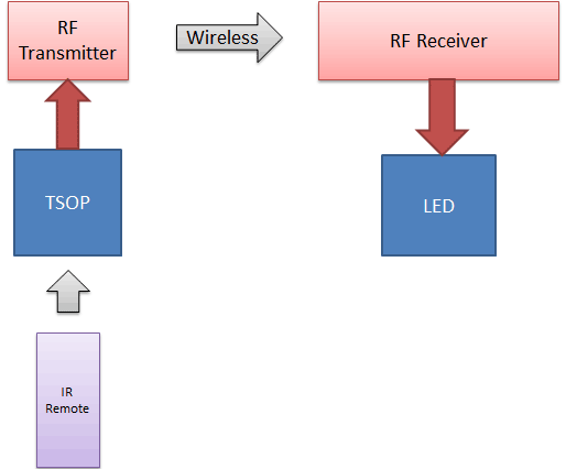
RF ASK Receiver further receives the converted RF signal, decode it and send it to LED through PNP transistor BC557. Now LED will glow according to incoming signal. LED is here for testing purpose and you can test the circuit by using any TV/DVD remote. When we press any button of IR remote, pointing towards TSOP1738, then the LED should blink.
Circuit Diagram:

Circuit of this project is very simple. TSOP output pin is connected to data pin of RF transmitter through a 100 OHM Resistor and data pin of RF receiver is connected at the base of BC557 PNP transistor through a 1K resistor. LED is connected at the collector of transistor.
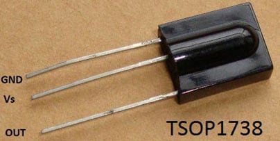
IR Receiver (TSOP1738):
TSOP1738 is working here as a IR detector or receiver. TSOP1738 reacts when it receives the IR radiation modulated at 38 KHz and TV/DVD remote generally works at 38 KHz frequency. TSOP’s output is active low, means its output is remains HIGH when there is no IR, and becomes low when it detects IR radiation. To know more about TSOP and its working check this project: IR Transmitter and Receiver
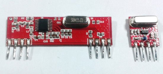
RF Transmitter and Receiver:
RF pair is used for wireless RF communication. There are other RF modules are also available like 3- Pin RF Module, so check their data sheet for proper connections. We here used ASK Hybrid receiver module working on 433 MHz and ASK hybrid transmitter module, shown in below figure. To know more about RF module and its working check this RF controlled Robot.
Comments
This is very simple circuit
This is very simple circuit and should work easily. Capacitor is not a problem, which RF pair are you using? There are other RF modules are also available like 3- Pin RF Module, so check their data sheet for proper connections.
include the Tx in TV Remote itself
Instead of using the IR TSOP, is it possible if the remote's IR LED signal is directly connected to the RF Tx module? since the Tx module is tiny enough it can be placed inside the remote cabinet itself thus avoiding additional supply to it too.
In this circuit may i use PIR
In this circuit may i use PIR sensor replacing the IR sensor??And which kind of antenna i will used to Tx. the data 500 meter to 1KM.?
What are the applications of
What are the applications of this circuit?
Can we use speaker as output
Can we use speaker as output instead of LED, as I am using this circuit as converter for IR audio transmitter "?
RC Drone
i have an RC Drone it is an infrared module so it has an problem like the infrared receiver should face the remote controle so i cant run the drone as like as possible sometime its out of my controle.... so can i use this circute to my drone directly by removing the ir receiver sensor (GND,VCC,OUT) and replace with the rf receiver module (GND ,VCC, DATA)

I have tried this , 100% followed the circuit diagram but it didn't work.
Not very good in electronics but a hobbyist.
Only thing i noted was i ave used 10uf capacitor with 63 volt rating because i coudn't get a lesser one.
Please reply.