

It is always interesting to build things that could be used in our day to day life and it gets more interesting when the same can be built easily at a very low cost. In this tutorial we will learn how to build a simple yet powerful MP3 player that could play any MP3 song, the volume and track can also be adjusted with the help of push buttons. With some extra effort you can build your own pocket MP3 Music player and take it with you on the go. Sounds interesting right, so let us build it.
Also check our Arduino Music Player.
Materials required:
- GPD2846 MP3 player Module
- 3 Push Buttons
- 3.3V Voltage regulator
- On/off button
- Speaker
- Breadboard
- Connecting wires
- 220K resistor
- Soldering kit
The list above might seem a bit long but they are all very cheap and easily available.
GPD2846 MP3 Module:
The heart of this mp3 player project is the GPD2846 MP3 Player Audio Decoder module. This module has a SD card slot in which we can insert an SD card with MP3 songs, and when we power the module it will start playing those songs. The module has four holes namely Battery Positive, Ground, Speaker positive and Speaker negative. It also has provision for three buttons which can be used to Play/Pause songs, Change track and Increase/decrease volume. The picture of the module with its pin-outs marked are shown below
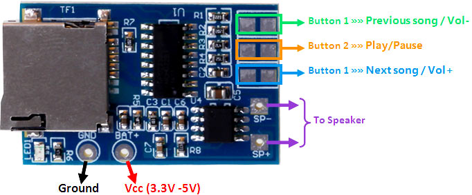
The Vcc pin can accept either 3.3V or 5V, but they should be regulated voltage. The speaker pins can be directly connected to any speaker; there is no need for any Amplifier circuit since the module itself in houses an Audio Amplifier.
As shown above there are options to use three buttons on the MP3 module. The functions of the button are shown below.
|
Button No: |
Short Press Action |
Long Press Action |
|
Button 1 |
Change to Previous Track |
Decrease Volume |
|
Button 2 |
Play / Pause the Song |
Change to FM (not used here) |
|
Button 3 |
Change to Next Track |
Increase Volume |
MP3 Player Circuit Diagram and Explanation:
The circuit diagram shown above will show how we can connect push button to the MP3 module so that we can control the track and volume.

We have used a 9V battery and a KIA78R Voltage regulator to regulate the battery’s 9V to 3.3V. A On/Off switch is connected to the trigger pin to Turn On or Turn Of the module. A 0.1uF capacitor is connected across the Vcc and Ground to filter noise. The speaker is directly connected to the SP+ and SP- pins.
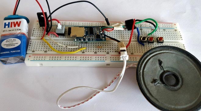
For connecting push button simply follow the schematics above, but you might want to solder some wires to make it breadboard friendly. The rightmost three terminals are pulled up to 3.3V using a 220K pull-up resistor. The three terminal boxes to the left are connect to ground through a push button. I carried out these connections a breadboard and my hardware looks like this
Working:
The working of this mp3 player circuit is very simple. Just insert the SD card with any number of MP3 songs and power on the module. You should see a red light going ON as soon as you power on, after few moments the LED will flash and the song will start playing. Once the song is over it will automatically move to next song. You can use the three buttons to control the track and volume as mentioned in the table above.
The complete working of the project is shown in the video below. Hope you understood the project and enjoyed building it. If you have any problem in getting this work post them in comment section below or on forums. Until then enjoy your music.
Comments
What problem do you have with the existing circuit diagram. It is clear enough to make your own connections. Let me know if you have any doubt
This is great project! Thank you for sharing. How difficult would it be to add a small LCD display with read out of song titles?
Thnks, this was very helpful.
Small error: The resistor in series with the button, it should be a 220 Ohm. I tried with 220k without success ;) Others tend to wire the button directly, but I prefer your cautious approach to limit a bit the current.
Thanks for pointing it out man, it should have been 220R instead of 220K
other than on off switch, r the 3 buttons momentary buttons?
also what is the 220R?
not much with electronics. but I can solder and read/follow simple schematics.
want to become more knowledgeable with electronics..
Is there a way to plug headphones in this board?
Thanks
Yes you can just add a 3.5mm jack to the speaker wires and use a headphone there
Hi! Thanks for sharing the info. I have a plush toy dog which earlier could play preloaded songs when you press the paws. Now i want to install diy mp3 player. So, my question is, if i want to use the paws e.g. left paw for turning on the player, right paw for next song and so on, how do i do it? I have the wires and switch taken out from the old toy. Can i just solder them into the the buttons as shown in the diagram? Thanks
Exactly!!
Just place the switch in the paws and run the wires to the MP3 circuit and it would work just fine
Thank you
Hi! I have another question (s). Q#1. I found a GPD2846A mp3 module where it says working voltage is 3.7v Li battery of 600Ma . In that case should i step down the voltage to 3.7v or 3.3v is alright? And what if i use the regular alkaline 3 X AAA batteries ( of nominal 1.5v) ? 3 batteries would come to total of 4.5v. so should I be using the 3.7v or 3.3v? Q#2. If its 3.7v, do i have to change the resistor value as well from 220 ohm to ??ohm? Q#3. I dont know what it means but the module mentioned a 2W mix mono. I found an 8ohm 1W speaker.. will it work? Q#4. Will it support microsd card when it says tf card support? Sorry for the asking too many questions. Im a newbie in electronics so i dont know much of anything and this will be my first project. Thanks
Hi, bro I want to make a external speaker for my laptop so,plz will u help me?
I have a 4 O 3W RxT speaker,so what are the components should I use?

Please provide me clear circuit diagram of mp3 player circuit..plz