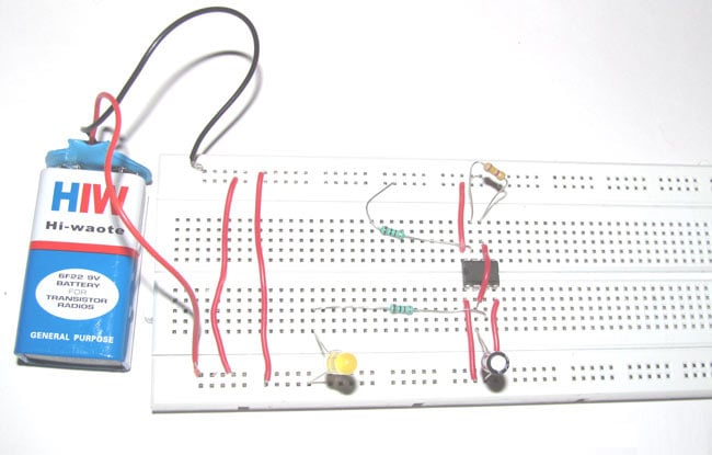
While getting started with electronics, you would like to make some simple circuits like a LED circuit to get acquainted with basic circuit designing concepts. Here is one 555 timer based circuit for you – An LED Flasher Circuit Diagram. Using some common easily available electronic components and an easy to understand schematic, this tutorial will show you how to make an LED glow and fade on a certain interval. So here is the step by step guide to make this flashing LED circuit.
Circuit Components
- 555 Timer IC
- 1uF Capacitor
- 470k Ohm Resistor
- 1k Ohm Resistors (2)
- 9v Battery
Circuit Diagram
555 timer IC is used here in astable operating mode which generates a continuous output in the form of square wave via pin 3 which turns the LED on and off. You can read here more about the different operating modes and basic concepts of 555 timer IC.
How to Make the LED Flasher Circuit: Step By Step
- Collect all the required components and get ready! Place the 555 timer IC on breadboard as per shown in the breadboard setup image given above.
- Connect pin 1 of 555 timer IC to the ground. You can see the pin structure of 555 timer IC in the pin diagram shown below.
- Connect pin 2 to the positive end of capacitor. The longer lead of a polarized capacitor is the positive and the shorter one is negative. Connect the negative lead of the capacitor with the ground of battery.
- Also connect the pin 2 with pin 6 of the 555 timer IC.
- Connect the pin 3 which is the output pin with the positive lead of LED using 1kΩ resistor. Negative lead of LED needs to be connected with the ground.
- Connect pin 4 with the positive end of battery.
- Pin 5 doesn’t connect with anything.
- Connect pin 6 with pin 7 using a 470kΩ resistor.
- Connect pin 7 with the positive end of battery using 1kΩ resistor.
- Connect pin 8 with the positive end of battery.
- Finally connect the battery leads with the breadboard to start the power supply in the circuit.
Once you connect battery in the circuit, it should flash the LED. If it doesn’t work, check the connections again. Also make sure that battery is connected properly in the breadboard and power is reaching to the components of circuit. Here you can change the flashing speed of LED by changing the capacitor with different capacitance. If you want to add more LEDs in this flashing LED circuit, connect them parallel with the first LED using proper resistors.
You can also connect more than one LEDs by using a decade counter IC 4017. Here is the detailed tutorial: Heart Shape Serial LED Flasher


Nice