
Sensors are very important part of electronics, especially in Robotics and Automations. Sensors in electronic devices make our life easy by automatically sense and control the devices, without human interaction. There are many kinds of sensors like Fire sensor, humidity sensor, motion sensor, temperature sensor, IR sensor etc. In this article, we will explain about IR sensor (Infrared sensor), how it works and how to build an IR sensor Module.
IR sensor is very popular sensor, which is used in many applications in electronics, like it is used in Remote control system, motion detector, Product counter, Line follower Robots, Alarms etc.
IR sensor basically consist an IR LED and a Photodiode, this pair is generally called IR pair or Photo coupler. IR sensor work on the principal in which IR LED emits IR radiation and Photodiode sense that IR radiation. Photodiode resistance changes according to the amount of IR radiation falling on it, hence the voltage drop across it also changes and by using the voltage comparator (like LM358) we can sense the voltage change and generate the output accordingly.
The placing of IR LED and Photodiode can be done in two ways: Direct and Indirect. In Direct incidence, IR LED and photodiode are kept in front of one another, so that IR radiation can directly falls on photodiode. If we place any object between them, then it stops the falling of IR light on photodiode.

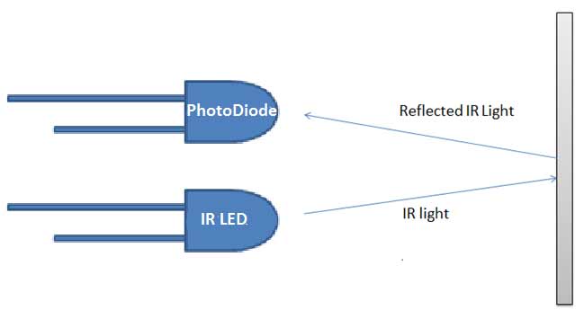
And in Indirect Incidence, both the IR LED and Photo diode are placed in parallel (side by side), facing both in same direction. In that fashion, when a object is kept in front of IR pair, the IR light gets reflected by the object and gets absorbed by photodiode. Note that object shouldn’t be black as it will absorb all the IR light, instead of reflect. Generally IR pair is placed in this fashion in IR sensor Module.
To build an IR module, we mainly need IR pair (IR LED and Photodiode) and LM358 with some resistors and a LED.
IR LED
IR LED emits light, in the range of Infrared frequency. IR light is invisible to us as its wavelength (700nm – 1mm) is much higher than the visible light range. Everything which produce heat, emits infrared like for example our human body. Infrared have the same properties as visible light, like it can be focused, reflected and polarised like visible light.
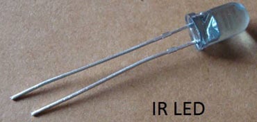
IR LED looks like a normal LED and also operates like a normal LED, it consumes 20mA current and 3vots power. IR LEDs have light emitting angle of approx. 20-60 degree and range of approx. few centimetres to several feets, it depends upon the type of IR transmitter and the manufacturer. Some transmitters have the range in kilometres.
PhotoDiode
Photodiode is considered as Light dependent Resistor (LDR), means it has very High resistance in absence of light and become low when light falls on it. Photodiode is a semiconductor which has a P-N junction, operated in Reverse Bias, means it start conducting the current in reverse direction when Light falls on it, and the amount of current flow is proportional to the amount of Light. This property makes it useful for IR detection.
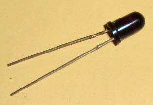
Photodiode looks like a LED, with a Black colour coating on its outer side. It is used in reversed biased, as showed in circuit diagram below.
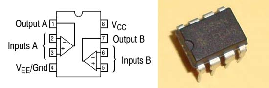
LM358
LM358 is an operational amplifier (Op-Amp) and in this circuit we are using it as a voltage comparator. The LM358 has two independent voltage comparators inside it, which can be powered by single PIN, so we can use the single IC to build two IR sensor modules. We have used only one comparator here, which have inputs at PIN 2 & 3 and output at PIN 1. Voltage comparator has two inputs, one is inverting input and second is non-inverting input (PIN 2 and 3 in LM358). When voltage at non-inverting input (+) is higher than the voltage at inverting input (-), then the output of comparator (PIN 1) is High. And if the voltage of inverting input (-) is Higher than non-inverting end (+), then output is LOW.
IR sensor Module
Components
- IR pair (IR LED and Photodiode)
- IC LM358
- Resistor 100, 10k, 330 ohm
- Variable resistor – 10k
- LED

You can see the connections in the IR sensor circuit diagram. Photo diode is connected in reverse bias, inverting end of LM358 (PIN 2) is connected to the variable resistor, to adjust the sensitivity of the sensor. And non-inverting end (PIN 3) is connected to the junction of photodiode and a resistor.
When we turn ON the circuit there is no IR radiation towards photodiode and the Output of the comparator is LOW. When we take some object (not black) in front of IR pair, then IR emitted by IR LED is reflected by the object and absorbed by the photodiode. Now when reflected IR Falls on Photodiode, the voltage across photodiode drops, and the voltage across series resistor R2 increases. When the voltage at Resistor R2 (which is connected to the non-inverting end of comparator) gets higher than the voltage at inverting end, then the output becomes HIGH and LED turns ON.
Voltage at inverting end, which is also called Threshold Voltage, can be set by rotating the variable resistor’s knob. Higher the voltage at inverting end (-), less sensitive the sensor and Lower the voltage at inverting end (-), more sensitive the sensor.
This whole circuit can be placed on PCB to build a proper professional IR sensor Module.
Comments
Hello. What is the best material to use as a reflector? Could a normal marble be used for example?
Super
plz..tell me what should be the setting value for variable resistor in this circuit....
plz help me in this
l
You can adjust it according to the sensitivity you need. Sensitivity means, from how far it should detect the object.
I tried making one but it wasn't working. At certain value of my potentiometer, the LED output is HIGH and becomes LOW when detects an obstacle. What could be the problem? I used all components just similar to yours. Thank you.
I tried making one but it wasn't working. At certain value of my potentiometer, the LED output is HIGH and becomes LOW when detects an obstacle. What could be the problem? I used all components just similar to yours. Thank you.
DEAR CONCERN,
EXCELLENT TUTORIAL.
FINALLY I SUCCESSFULLY ASSEMBLED THE PROJECT
THANKS A LOT ALL OF YOU AND YOUR FAMILY
Thanks alot... It help us great deal ..
can this be used in arduino
thank you for the circuit and design part.
what is the function 330ohm resistor here
I am currently living in the Philippines and wantedto do a laser tag set up for the neighbor kids. I have a basic knowledge of electronics but do not know how to form the necessary circuitry to both send ir and detect ir to make the plastic guns work. Can you point the way? No need to reinvent the wheel if someone has done this already.
hello my circuit is not working just led is on but I can not do any measurement
This circuit working well but distace of reflection still short, help me to get solution that can make distace of IR LED can longer and reflect more far of distance (ex: 1 meter). I need your help, I wait your reply by email.Thx.
is that output pin connected to arduino's digital pin?
Hi,
I really do appreciate your job!!!
you helped me a lot! Thanks
Hey there,
I think that this sensor has a limited sensibility, am i right?
if yes how can i increase it?
What do you mean by sensibility here?
If you are talking about the range, then sorry nothing much can be done to improve it.
Your circuit is superb . But it detection range is small. How I increase it's range. I mean how I make long range IR module circuit ? Please say.
I am waiting for your email .
The range of the IR sensor can be controlled by changing the reference voltage of the op-amp. In this circuit, the potentiometer can be varied to change the reference voltage.
what is distance can measred
Could you please explain me what is the need of ground this circuit.
Hi Hritika,
Its not just this circuit, every circuit will need a ground. As we know current always flows from positive to negative, this negative potential is usually referred as ground.
Hi, can i use a 9v batt here or should i use Lm7805 to decrease my 9v batt to 5v?
-Is the operational amplifier inverting or non inverting?
-Would another model of Operational amplifiers work as well? If so which do you recommend. Does the TL084CD work too?
-Where would be best to obtain these elements?
Amazing
V output when high is equal to Vf LED ~2V
to send signal to arduino input pin, should take from pin 1 on LM358 where high will be 5V.
Hi,
this is superb circuit diagram, but i want to modify it when there is a obstructed the LED goes ON and it goes to OFF only when a reset button is pressed. could you please help me to giving the reference.
Thank you.
is there any other ic or any other element that could be used in place of LM-358
Hello Jayant,
That seems great work !!
i have made it and can work as shown in video :)
BTW, how can i increase the distance from object to IR photo diode (about 30 cm).?
super explanation.thank you
how to set off time even an oscillate in front of the sensor ?
can IR be reflected by paper like and envelope? I am trying to install this inside my mailbox to detect if there is a mail inside
Yes IR will reflect paper and envelop. You can use it for your idea
is the IR led a transmiiter or receiver?
Hi,
I actually don't understand how the current would flow in the circuit of the IR module using LM358 voltage comparator. It would be very kind and helpful of you if you could tell me the current flow and what is the reason of current flow in one direction and not the other.
I get a bit confused in parallel circuits.
Thank You
Very good in detail and well illustrated Jayant. Couldn't have asked for more. Look forward to more of your articles.

waow ..this is good information about IR . I have been searching for something like this