
Mobile phones generally charge with 5v regulated DC supply, so basically we are going to build a 5v regulated DC supply from 220 AC. This DC supply can be used to charge mobiles as well as the power source for digital circuits, breadboard circuits, ICs, microcontrollers etc.
You can also build 6V DC, 9V, 12V, 15V etc by using proper transformer, capacitor and voltage regulator. The basic concept remains the same, you just need to arrange a heat sink for higher voltage and current.
This circuit mainly consists a step down Transformer, a Full wave bridge rectifier and a 5V voltage regulator IC (7805). We can divide this circuit into four parts: (1) Step down AC voltage (2) Rectification (3) Filtration (4) Voltage Regulation.
1. Step down AC voltage
As we are converting 220V AC into a 5V DC, first we need a step-down transformer to reduce such high voltage. Here we have used 9-0-9 1A step-down transformer, which convert 220V AC to 9V AC. In transformer there are primary and secondary coils which step up or step down the voltage according to the no of turn in the coils.
Selection of proper transformer is very important. Current rating depends upon the Current requirement of Load circuit (circuit which will use the generate DC). The voltage rating should be more than the required voltage. Means if we need 5V DC, transformer should at least have a rating of 7V, because voltage regulator IC 7805 at least need 2V more i.e. 7V to provide a 5V voltage.
2. Rectification
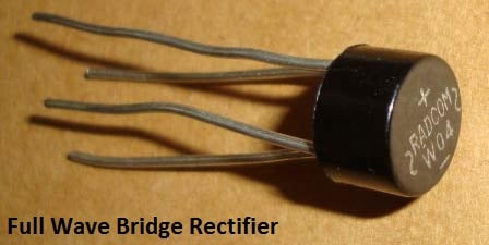
Rectification is the process of removing the negative part of the Alternate Current (AC), hence producing the partial DC. This can be achieved by using 4 diodes. Diodes only allow current to flow in one direction. In first half cycle of AC diode D2 & D3 are forward biased and D1 and D4 are reversed biased, and in the second half cycle (negative half) Diode D1 and D4 are forward biased and D2 and D3 are reversed biased. This Combination converts the negative half cycle into positive.
A full wave bridge rectifier component is available in the market, which consist that combination of 4 diode internally. Here we have used this component.
3. Filtration
The output after the Rectification is not a proper DC, it is oscillation output and has a very high ripple factor. We don’t need that pulsating output, for this we use Capacitor. Capacitor charge till the waveform goes to its peak and discharge into Load circuit when waveform goes low. So when output is going low, capacitor maintains the proper voltage supply into the Load circuit, hence creating the DC. Now how the value of this filter capacitor should be calculated. Here is the formulae:
C = I * t / V
C= capacitance to be calculated
I= Max output current (let’s say 500mA)
t= 10ms,
We will get wave of 100Hz frequency after converting 50Hz AC into DC, through full wave bridge rectifier. As the negative part of the pulse is converted into positive, one pulse will be counted two. So the Time period will be 1/100= .01 Second= 10ms
V = Peak voltage – voltage given to voltage regulator IC (+2 more than rated means 5+2=7)
9-0-9 is the RMS value of transforms so peak voltage is Vrms * 1.414= 9* 1.414= 12.73v
Now 1.4v will be dropped on 2 diodes (0.7 per diode) as 2 will be forward biased for half wave.
So 12.73 – 1.4 = 11.33v
When capacitor discharges into load circuit, it must provide 7v to 7805 IC to work so finally V is:
V = 11.33 – 7= 4.33v
So now C = I * t / V
C = 500mA * 10ms / 4.33 = .5 * .01 / 4.33 = 1154uF ~ 1000uF
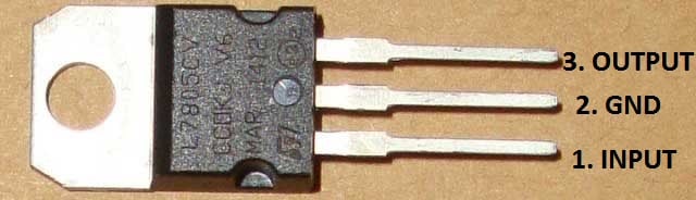
4. Voltage Regulation
A voltage regulator IC 7805 is used to provide a regulated 5v DC. Input voltage should be 2volts more than the rated output voltage for proper working of IC, means at least 7v is needed, although it can operate in input voltage range of 7-20V. Voltage regulators have all the circuitry inside it to provide a proper regulated DC. Capacitor of 0.01uF should be connected to the output of the 7805 to eliminate the noise, produced by transient changes in voltage.
Here is the complete circuit diagram for cell phone charger circuit:

You need to be very careful while building this circuit, as AC mains 220V is involved here.
Comments
Good brother i think the schematic is clearly given on this page(:
Sir i don not know how to connect transformer to the circuit.
What is output of circuit
If lower than 2A how to get it there
It will depend upon the Transformer, here 9-0-9 1A Transformer is used.
Hi. I'm making a similar circuit and would just like to know the specifications of the full wave bridge rectifier used above.
Thank you
sir what's value of C2
Its mentioned in circuit diagram, its 0.01uF (capacitance code 103)
Hi
I'm making a similar project. I'd just like to know whats the model of the rectifier that you've used.
Its 400v 1A Full Wave Bridge Rectifier, can be easily available on any electronics components shop or online stores like ebay.
How can this circuit be adapted in a locality where voltage fluctuate. What is the efficiency?. From your figure, the voltage measured was 5.11v. How about over voltage, overcurrent protection?ī
I think you have drawn the circuit incorrectly. The way you've drawn it, diodes D1 and D3 short out the transformer output on negative cycles. Your circuit has the junction of D1 and D3 is connected to the transformer centre-tap, although that's not very clear the way you've drawn it.
You need to remove D1 and D3 completely, and the circuit will then work as you meant it to. You do not need and should not use a bridge rectifier with a centre-tapped transformer.
The other way to fix your circuit is not to connect the centre-tap of the transformer to ground, but then you'll have 18v AC across the bridge, which will be about 25v DC, and the regulator will then dissipate a lot of heat.
Also, you should put a 0.1uF or 0.01uF capacitor on the input side of the regulator as well as the output side.
With the transformer shown as connected in the schematic (ie 9-0-9 - centre tap), you do not need & should not use a bridge rectifier, the common earth on the -ve side of the rectifier and the centre tap will sohort circuit one of the windings. If you use a single winding transformer, use a bridge rectifier; if you are using a cenrre tap transformer, use 2 individual rectifer diodes thus: the centre tap of the transformer is used as the -ve supply to the circuit & the two other winding ends go through the diodes which are commoned to gether at their + ends. This commoned connection is the +ve supply to the circuit.
How to designe a power supply used for mobiles in which rectifier is used before TRANSFORMER.
Good
SIr i need help designing a power supply unit that has 5V DC output with 2A. Requirements sais i must use a supercapacitor so that the unit will continue to provide electrical energy for 2 minutes even if the unit is unplugged. I hope i can get a response. Thank youuuu
I tried this circiut and output is 2.2v i need 5 volt when i missed pls help me iam Mongolia
Hi Bat-Erdenr,
Could you provide more detail information about your question? Was your experiment result 2.2V? Did you use exactly same components which drawn on this circuit?
Good day sir! I need to build a 220Vac – 5Vdc, 2A linear power supply. Which of your components do I need to change to accomplish this? Thank you!
I shall try make this charger
Thank you for setting
I need the output to be 9V and 1.2A. How do I regulate or set the current at the output to 1.2A?
I guess the 78xx series IC's have a maximum current of 1A. Should I use an LM317?
Can I control current at output using additional circuitry?
What about inverter
This is a 5V adaptor not charger.
charger circuit is inbuilt in phone which gives 4.2V to battery and does cc+cv+trickle charging.
Sir, i want to make adapter with output 5V , 1A.. please guide me which changes i have to do in above circuit. Thank you.
How can we increase 1a to 3a
help in making a 5v 2a adaptor like this
@Parag, @Cvbjjv, @Banjo: First you should select the Transformer accordingly, and then you need to select components, that can bear the current according to the Load, so that they wont burn up. Like roughly IC7805 can handle 1A current, depending upon the load.
Hello
how to make multiple mobile charger at least 10 mobiles charge at once.
How to make the output becomes 12 V?
Will this circuit still work if i replace the transformer . and make it like in a wireless charger, transmitter coil- receiver coil?
Could you run a phone charger, or any AC/DC adapter, backwards to attach a battery to the output leads and get AC out of the plug?
Bob Clark
i just have a stu[pid question..can i use the transformer found in the cellphone charger the opposite way?
@Robert @Melchor: You are talking about the inverter circuit, converting DC into 110/220v AC, check this circuit: 12v DC to 220v AC Inverter Circuit
Is it okay to use 5v zener diode and 1k ohm resistor to disipate the ripples?
My cell phone charger out put voltage only .3 volt.It is not desirable.But i can not under stand the problem .Please answer me
Dear Sir,
I am trying to make mobile charger using wind energy. I also prepared circuit with diode BR10-10, 1000UF/35V CAP., 7805 IC nd 10UF /63V cap. But I am getting only 2mAmp in place of 500mAmp. How can I achieve it? please help me. Nd I also use 500RPM - 12V DC Motor as generator.
How can I get an output current of 2 amps with 5v/any other voltage ....what are the changes to be made in the circuit toooo....please explain....????
Hi Jagadeesh, check this Circuit for high Current output: 0-24v 3A Variable Power Supply
Hey I want the circuit design for making mobile charger........
hey everybody...i want to design a multiple current ratings charger of values 1A 1.5A 2A....IN A SINGLE BOX...any knowledge about this project ???seriously neede.....
Hello,
i have a generator producing 8V AC 3 phases (3 wires) and i would like to charge my phone at 5V 1A DC
Can i skip the step 1 and directly go to step 2 ?
And how did you calculate the 100 Hz ?
Thank
Yes you can skip step first but you also need to consider the current rating your Generator. And AC is of 50Hz so we get 100Hz in DC.
I need a charger circuit without any tranformar
check this one: Transformerless Power Supply
Sir I want to make charger 5v to 12v Regulated output. what changes are required in this circuit? if we used SCR instead of Diodes what will the result?
Check this one: 0-24v 3A Variable Power Supply using LM338
How to prepare mobile phone charger without any transformer??
I want to prduce modulated phone wave from 1000 to 2500 Hz . and to be able to tune its intesity for biological stuy
many thanks
I am trying to make a simple water level indicator using the data taken from internet only. i just wanted to know whether i could replace 9V 1A ac adapter in place of using 9V HW battery for making a simple water level indicator which has resistor 330 ohms and transistor BC 547 in it.
As in transformer o/p power =i/p power then how the electronic devices are working at our homes because of this high i/p power of a transformer.
how to 5v ?
Good Day Sir,,
what transformer should i use in reducing AC 85 - 270 v.
How do i use a transformer with 11v output
You can use 11v transformer with this circuit, current rating should be less than 1A, what is the current rating of your transformer?
Sir,
Please tell me why my mobile charger is showing charging but battery is not charging what could be the problem in any mobile?
Hello sir i need sm help please
i hv transformer now its giving me dc output is near 13v but i wanted to charge my my 2.4v Ni-mh battery so i used 8v mosfet or i think its called as voltage regulator LM7808 and created a circuit but did not work my battery isn't charging...(i checked it using multimeter it gives 7.98v) but its not working at all i dont kno why i need sm solution or is thr any way to increase output voltage of mobile charger like my android charger gives 5v output so if i can increase it to 7-9 v ? please help me out
i want to make charger thats gives at digit dc voltage between 7-10 v dc so i can charge my2.v battery using it
it wud be a big help of some1 show me how to increase voltage of normal mobile charger
thank you
Check this one: 12v Battery Charger Circuit using LM317
i have done it but the percentage of battery coming down, what could do to up the percentage
which capacitor can i use when designing a mobile charger AC12 input?
What should we have to do if we need output current of 2A
Input is 100-220v~ 50-60Hz 1.5A
Output 19V=4.74A
good day sir..
may i know, what is the function for C1 capacitor?
thank you.. sorry for my bad english..
sir i want to make a fast charger which out put has 5 volt and 3 amp, do you have any diagram ?????????
i have already 3500 map lipobattrie
Thank you Sir, I have copied the end of the circuit, after the bridge rectifier, because I don't need it as I am using a DC Motor. The Motor is rated 12V so the Voltage Regulator with the same Capacitors should do the job nicely, providing a 5V output to a mobile phone or power bank. Would I put a 100ohm resistor in my final circuit?
How many ampere it gives at output ?
why you didn't used a resistor in smoothing?
Sir you just made my concepts better,
Thanku
All chargers av seen contains resistors in them , why is that ?
How does enough current get to her to electrocute her even if she is in the tub considering its a mere 5v @ 0.2a??
Sir,
What happen if I connect a 7V DC motor directly to a 220V AC supply by a charger and datacable
Is it work or get any short circuit???
Assuming your chargers output to be 5V 2A. Yes you can do it. It will not create a short circuit.
But, it is not an effective way of doing it. Because the 7V motor will be powered by 5V which will force it to consume more current and eventually damage it.
So this will be a temporary solution only.
i need block daigram and circuit daigram power supply. one input and meny outputs.but output current will be different
LED in mobile charger is not glowing and mobile also is not charging..so, i want to take a risk of removing LED and joining both ends..will it work..what is the significance of LED apart from glowing indication..?
LED is given for indication purpose. Removing it might not help.
Which LED are you talking about? There is no LED in the circuit diagram
1 Hors 80 % Mobaile Chargin & All Compny Mobaile Charge ?
i want to know that is it the mobilecharger using buck converter or not?? pls clarify
good and simple
what if 2A transformer is used ????
Yes you can use a 2A transformer, it will increase the output current of the circuit. But since 7805 can supply only upto 1.5A you will not be able to draw more than that without damaging the IC
Plz,tell me how to connect a charger with USB.
Cut the charging cable of any old charger and find the positive and negative wire in the cable and connect it to the circuit.
However this circuit is only for educational purpose and is not intented to be used for practical applications without any modifications
is the above mentioned circuit unsufficient for a practical use? what else are necessry ? and why
how can we make our resolution stable enough for example if the input ac voltage changes?

i need a charger circuit