
Simple Mic audio amplifier can amplify sound that is given from Microphone. This circuit can be used as “Small mic and loudspeaker system” for a small space like a room. This circuit can also be used in many applications like portable music players, intercoms, radio amplifiers, TV sound systems, Ultrasonic drivers etc. It can also be used as sound sensor for microcontrollers. It is inexpensive, low power operated and only need few components to work. This circuit is based on LM386 IC to amplify sound.
LM386 is a low voltage audio amplifier and frequently used in battery powered music devices like radios, guitars, toys etc. The gain range is 20 to 200, gain is internally set to 20 (without using external component) but can be increased to 200 by using resistor and capacitor between PIN 1 and 8, or just with a capacitor. Voltage gain simply means that Voltage out is 200 times the Voltage IN. LM386 has a wide supply voltage range 4-12v. Below is the Pin diagram of LM386.
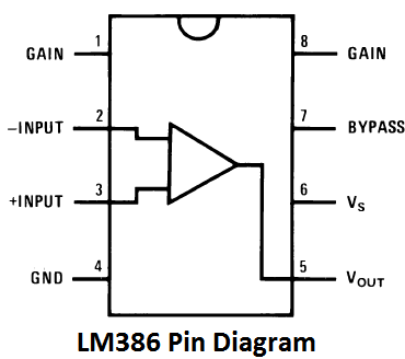
Pin description of LM386 is given in the following sections along with the functions of external components used for amplification. So let's start building our simple LM386 based audio amplifier circuit design.
Components Required for LM386 Audio Amplifier Circuit
- IC LM386
- Condensor Mic
- Speaker 8ohm
- Capacitors- 220uF, 10uF (two), 0.1uF, 0.05uF
- Resistor- 10k (two)
- Potentiometer- 100k
- Battery 5-12v
PIN 1 and 8: These are the gain control PINs, internally the gain is set to 20 but it can be increased up to 200 by using a capacitor between PIN 1 and 8. We have used 10uF capacitor C1 to get the highest gain i.e. 200. Gain can be adjusted to any value between 20 to 200 by using proper capacitor.
Pin 2 and 3: These are the input PINs for sound signals. Pin 2 is the negative input terminal, connected to the ground. Pin 3 is the positive input terminal, in which sound signal is fed to be amplified. In our circuit it is connected to the positive terminal of the condenser mic with a 100k potentiometer RV1. Potentiometer acts as volume control knob.
A capacitor C5 of 0.1uF has also been used along with potentiometer, to remove the DC component of input signal and only allow audio (AC component) to be fed into LM386.
Pin 4 and 6: These are the power supply Pins of IC, Pin 6 for is +Vcc and Pin 4 is Ground. The circuit can be powered with voltage between 5-12v.
Pin 5: This is the output PIN, from which we get the amplified sound signal.
The output signal has both AC and DC component, and DC component is undesirable and can’t be fed to Speaker. So to remove this DC component, a capacitor C2 of 220uF has been used. This has the same function as Capacitor C5 (0.1uF) at input side.
Along with this capacitor, a filter circuit of Capacitor C3 (.05uF) and resistor R1 (10k) has been used at the output PIN 5. This filter also called the “Zobel network”, this electronic filter is used to remove the sudden High frequency oscillations or noise.
Pin 7: This is the bypass terminal. It can be left open or can be grounded using a capacitor for stability.
LM386 Audio Amplifier Circuit Diagram
Below is the schematic diagram given for this LM386 IC based audio amplifier.

Resistor R2 (10k) has been used as a Pull up resistor to connect Condenser mic to the positive supply voltage, to provide the power to the mic. A suitable resistor should be used for proper working of mic, you can look up to datasheet for the value or use a variable resistor and set the proper value.
This LM386 audio amplifier circuit can be also used to record any sound. We just need a 3.5 mm audio plug and a computer with sound recording software. We only need to connect computer’s 3.5mm jack in place of Speaker, using 3.5mm audio plug, and we can easily record our voice or any sound into computer like a professional microphone. [Also check: Simple Audio Amplifier using IC 555]
Comments
Nothing is wrong, we have
Nothing is wrong, we have just used two 0.1uF ceramic capacitors in series, to get the 0.05uF (1/C = 1/C1 + 1/C2). If you have 0.05uF capacitor, you can directly use that one. Go with circuit diagram.
Its a normal 100k
Its a normal 100k potentiometer (variable resistor).
condensor mic is same as
condensor mic is same as buzzer in proteus ????
No, you should use Signal
No, you should use Signal generator and generate square wave for simulate a clap sound in Proteus. It is just a representation of mic in circuit diagram, which looks like a Buzzer.
yes, you can use mobile phone
yes, you can use mobile phone audio output.
R1 is 10k, means 10 thousands
R1 is 10k, means 10 thousands ohms.
Of course, you should follow
Of course, you should follow circuit diagram. Project Image is also following the Circuit diagram.
small loudspeeker
I want to know the detail working of this circuit for my mini project. I a help of any one immediately.
What is the output current.
What is the output current. Of your circuit from the speaker.
It would be about 350mA,
It would be about 350mA, check LM386 datasheet for more info.
sir, would like to mention
sir, would like to mention that u have used a 10K resistor as R2.
if u use a 47k or 56k resistor instead of it the microphone would work more efficiently and would become more sensitive.
and i would like to ask.
about the capacitor C3 and C5. what value can i use if i dont have both of them???
please help me soon..
You can use two 0.1uF
You can use two 0.1uF capacitors in series, in place of 0.05uF capacitor. Because, in series, capacitors are added like this 1/C = 1/C1 + 1/C2 ...
R1 is wrong
In your circuit R1 is marked 10k, 10,000 ohms. This is WRONG . It is part of the Zobel network to aid stability into inductive loads (speaker/headphones) and should be a low value. As Ger said above, R1 should be 10 ohms. Check the LM386 data sheet for confirmation.
Can i use 47kohm
Can i use 47kohm potentiometer in place of 100k
If no what are its effects
CAN I USE , SPEAKER 8 OHM 0,5
CAN I USE , SPEAKER 8 OHM 0,5 WATT?
Yes, in fact the speaker used
Yes, in fact the speaker used is 8 ohm 0.5 watt.
LM386 amplifier
Dear Sir, I would like to use the amplifier for hearing aid. In this case the loudspeaker must be replaced by a crystal earphone, what changes must I make in the circuit? Kind regards.
negative feedback
what if i want my circuit to have negative feedback and overall gain with feedback = 1000?
LM386 has gain range upto 200
LM386 has gain range upto 200 only.
rectification
i am in nigeria so my voltage needs to be rectified to prevent my circuit from burning. What do i do?
i placed a signal generator
i placed a signal generator instead of a mic in my proteus but it does not simulate because of excess CPU load. I have changed my resistors to pull-up and tried everything. Pls what is wrong
Although signal generator is
Although signal generator is generally used as replacement for Mic in proteus but there are some custom Libraries for Mic, just search them.
want to change something
Do I afix a audio 3.5mm Jack instead of mic?
Check this one to take input
Check this one to take input from 3.5mm jack: Small Loudspeaker for Computer or Cell Phone
Is there any programming for
Is there any programming for arduino in this project
here u ve selected a 10 k
here u ve selected a 10 k resistor as a impedance equalizer resistor (Zobel resistor ) when i seeked through the net i found it to be 10 ohm using the online zobel resistance calculator.
what do u wanna say?
Electrical
Am doing a project on loadshedding time management using programmable interface.using the arduino uno.I need help on the connection.
Can you send circuit backside
Can you send circuit backside image
For wiring plz
Can I have the detail
Can I have the detail calcification for the design of the circuit?
condenser mic value
please tell me the required values of the condenser mic
Electronic stethoscope
Hello,
I am using this circuit for an electronic stethoscope.I have inserted the condenser mic inside the acoustic stethoscope's chest-piece. Instead of a speaker, there is an audio jack to which any earphones can be plugged in. After rigging it up and while testing there is a constant hissing noise in the background. Adjusting the potentiometer only agravates the noise! What should I do?
Signal distortion
Can you please provide the formulas to calculate your gain in dB and also to calculate your signal distortion for this circuit?
power supply voltage?
what is the voltage of power that i can use in this circuit and where i should connect the power supply?
If the pot value is maximum
If the pot value is maximum what is output frequency range?
electronics
why we r using 220uf capacitor. instead of 220uf we r using 470 uf but the noise high ?what is the difference between the capacitors.
low frequency amplifier with out put led
led which can be detected by eye
sir can you provide the
sir can you provide the calculations how we choose r1 c1 etc.i need the design pls help me .

Why from your diagram..I count there are 3 ceramic capacitors and 3 electrolyte capacitors..? But from what you mentioned in the list, there are 5 capacitors used.. then what is the value of the other ceramic capacitor in the diagram ?? Is it you listed it wrong ?????
Please help me !!!