
A seven-segment display (SSD) is a widely used electronic display device for displaying decimal numbers from 0 to 9. They are most commonly used in electronic devices like digital clocks, timers and calculators to display numeric information. As its name indicates, it is made of seven different illuminating segments which are arranged in such a way that it can form the numbers from 0-9 by displaying different combinations of segments. It is also able to form some alphabets like A, B, C, H, F, E, etc.
7 segment displays are among the simplest display units to display the numbers and characters. As shown in the above image of a 7-segment display,  it consists of 8 LEDs, each LED used to illuminate one segment of unit and the 8thLED used to illuminate DOT in 7 segment display. We can refer each segment as a LINE, as we can see there are 7 lines in the unit, which are used to display a number/character. We can refer each segment "a,b,c,d,e,f,g" and for dot character we will use "h". There are 10 pins, in which 8 pins are used to refer a,b,c,d,e,f,g and h/dp, the two middle pins are common anode/cathode of all he LEDs. These common anode/cathode are internally shorted so we need to connect only one COM pin.
7 Segment Display Pinout
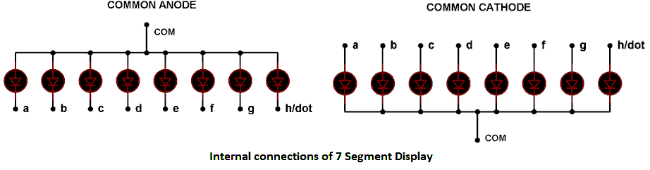
There are two types of 7 segment displays: Common Anode and Common Cathode:
Common Cathode: In this all the Negative terminals (cathode) of all the 8 LEDs are connected together (see diagram below), named as COM. And all the positive terminals are left alone.
Common Anode: In this all the positive terminals (Anodes) of all the 8 LEDs are connected together, named as COM. And all the negative thermals are left alone.
How to Display Numbers on 7 Segment Display?
If we want to display the number “0”, then we need to glow all the LEDs except LED which belongs to line “g” (see 7 segment pin diagram above, so we need a bit pattern 11000000. Similarly to display “1”we need to glow LEDs associated with b and c, so the bit pattern for this would be 11111001. A table has been given below for all the numbers while using Common Anode type 7 segment display unit.
| Digit to Display | h g f e d c b a | Hex code |
| 0 | 11000000 | C0 |
| 1 | 11111001 | F9 |
| 2 | 10100100 | A4 |
| 3 | 10110000 | B0 |
| 4 | 10011001 | 99 |
| 5 | 10010010 | 92 |
| 6 | 10000010 | 82 |
| 7 | 11111000 | F8 |
| 8 | 10000000 | 80 |
| 9 | 10010000 | 90 |
To learn more about 7 segment display units, read below tutorials which explains the practical applications to use 7 segment displays:
Interfacing 7 segment display with 8051 microcontroller
My project need to use 4 traffic light and 4 counter.. And it used a lot of pin.. How can i program it to make it use less pin.. Currently right now i have to used more than 15 pin and arduino did not have that much..
Use Four digit Seven segment display, like here: 7 Segment Display Interfacing with PIC Microcontroller
In the text describing common anode / common cathode, I think you have the description exactly backwards. The diagrams just below that look correct. Otherwise, a very helpful article, thanks!

good