
If you are exploring the world of electronics, and you want to know more about the Transistors and MOSFETs for your upcoming brilliant project, you are at the right place. In this article, we will discuss the basics of BJTs, Transistors, and MOSFETs. Before semiconductors (particularly transistors), the only devices available for signal amplification and switching were Vacuum Tubes. And when I say vacuum tubes, the first thing that comes to the mind is a big bulky device, inside which the vacuum tubes reside. They require a high operating voltage (they eat a lot!) so unfortunately for them, society rendered them inefficient employees and they got fired. Transistors are the new employees, and well, so far so good! The burning question then is, between BJT and MOSFET, who should win the employee of the year award?
Previously, we have built many projects that require BJTs, Transistors, or MOSFETs to work properly. You can check those about if you are interested in making cool projects with them. We also made a tutorial on Vacuum Tubes, you can also check that out if you want to learn more about it.
Let’s welcome our first candidate – The BJT
Bipolar Junction Transistor (BJT) was invented in 1948 at Bell Telephone Laboratories. The bipolar in the name signifies the fact that both holes and electrons are used in this transistor for current conduction. Like any transistor, BJT can amplify a signal or switch a high power load using a very small signal. In terms of the architecture of BJT, three big terms come to play. They are regions, junctions, and modes of operation. BJT is divided into three regions based on doping. It has the Emitter Region, which is highly doped. The slightly doped Base Region and the Collector Region which is moderately doped.
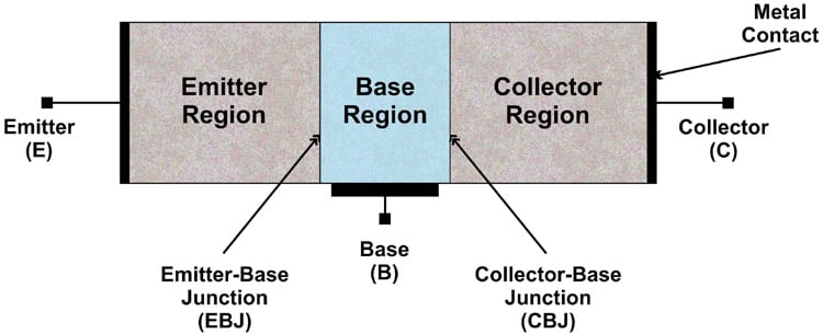
The second term is junctions. Every BJT has two P-N junctions called the Emitter-Base junction (EB) and the Collector-Base Junction (CB). Depending on the biasing of these two junctions, the BJT can operate in different modes.
|
Mode of Operation |
EBJ |
CBJ |
|
Cut-off (used for switching) |
Reverse-biased |
Reverse-biased |
|
Active (used for amplification) |
Forward-biased |
Reverse-biased |
|
Reverse-active |
Reverse-biased |
Forward-Biased |
|
Saturation (used for switching) |
Forward-biased |
Forward-biased |
BJT, why should you be named the better transistor?
Well, BJTs are not easily damaged by static electricity, they are cheaper and easier to bias than MOSFETs. BJT is the more robust candidate. They are a preferred option for low-current applications like switching a low-current relay, LEDs, and amplifiers.
We call the BJT a switching device because it does not consume a lot of power to provide regulation. You might ask, “How does it do this? Is it from outer space? “Well, the answer is simple. To work as an open switch, a BJT operates in cut-off mode, here there is zero collector current, meaning ideally zero power is consumed by the BJT. On the other hand, to work as a closed switch, a BJT works in saturation mode, there are a high collector current and zero collector voltage, meaning ideally there is zero power consumed by the BJT.
Remember the sentence, “They are a preferred option for low-current applications”? Highlight the term, low-current. BJTs are high-voltage, low-current devices. This means, under normal operating conditions, a BJT can handle tens of amps while withstanding up to one thousand volts and more.
Thank you candidate one.
Now, let’s move on to the second candidate - MOSFET
MOSFET stands for Metal Oxide Semiconductor Field Effect Transistor. It may sound like combining 5 words just to name a single device is a little too extra, but the name makes perfect sense as it describes both the structure and the working of the device.
The Metal Oxide – A MOSFET has three regions, the source, the drain, and the gate. It is made up of a doped semiconductor. The two regions, the source, and the drain are placed on top of the doped semiconductor. Between the source and the drain, there is an oxide layer that acts as an insulator. On top of the oxide layer, there is a metal plate to put the gate structure. This is why the name has metal oxide in it.
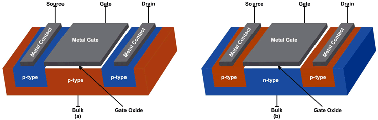
The Field Effect - The name explains how this transistor works. Recollect that the structure of the MOSFET is such that the gate region is placed on top of the insulating oxide layer. This makes the gate to be electrically isolated from the rest of the circuit. It being electrically isolated, however, does not prevent it from being able to control the flow of current from the source to the drain. Again, the question is “HOW?” When there is a voltage applied across the gate-source, an electric field is established, which controls the conducting path between the source and the drain. This is why a MOSFET is known as a type of F.E.T
Lastly, a MOSFET, unlike BJT, is a unipolar transistor. Meaning that conduction of current is through either the flow of electrons (N-Channel MOSFET) or it flows through the holes (P-Channel MOSFET).
MOSFET, why should you be named the better transistor?
For starters, MOSFETs have faster switching speeds and lower switching losses than BJTs. BJTs have switching frequencies of up to hundreds of kHz, while MOSFETs can easily switch devices in the MHz range. So, for high-frequency applications where switching losses have a major role in the total power loss, MOSFET is preferred. For digital circuit designers, the dimensions of MOSFET can be scaled down with lesser fabrication costs than BJTs. MOSFETs are highly used in memory devices such as microprocessors. Which transistor is used in a CPU? FinFETs, which are a type of MOSFET transistors.
Yes, MOSFETs are more costly than BJTs. Their higher price tag is well-spoken as they do not suffer from a secondary breakdown issue like BJTs. They also have a positive temperature coefficient for resistance, this makes parallel operation easy. Parallel operation is a design technique that comes in handy when one wants to increase the power handling capacity in the circuit. It is just connecting transistors in parallel when the current in the circuit is more than what can be handled by one transistor.
MOSFETs have easier to design gate driver circuits than the BJT’s base driver circuit. The reason for this is that generally in electronics, it is easier to supply a constant voltage than it is to supply a constant current. So, fortunately for MOSFETs, since they are voltage-controlled devices, they become easier to drive. BJTs on the other hand, are current-controlled devices so, things are a bit complicated for them.
Thank you candidate two.
A Quick Comparison of BJT vs MOSFET
|
BJT |
MOSFET |
|
It is bipolar |
It is unipolar |
|
It is a high-voltage, low- current device |
It is a low-voltage, high-current device |
|
Lower switching speed |
High switching speed/frequency |
|
Hard to drive |
Easy to drive |
|
Cheaper |
More expensive |
|
Robust |
Easily damaged by static electricity |
|
Easy to bias |
Difficult to bias |
|
Has a secondary breaking issue |
No secondary breaking issue |
|
Negative temperature coefficient |
Positive temperature coefficient |
|
Suitable for low-current applications |
It is suitable for high-current and high-frequency applications |
Which one is better?
Some say BJT, while others say MOSFET. People have different answers because they use them for different applications. For example, BJTs are better in low-current applications, while MOSFETs are better in high-current applications. To choose which transistor better suits your project, properly evaluate the key parameters of your project like budget, the switching speed required, the maximum voltage, and current ratings of the project. Based on these, one can then select the best employee (either MOSFET or BJT) for the task.
