

Nowadays, Switching Mode Power Supply or SMPS is used in nearly all electronic devices. That's why as an electronic engineer, it becomes important to understand the concept of voltage mode power supply and current mode power supply and the use cases in a practical scenario. Voltage mode and current mode supplies are simply the two regulating condition that determines the output of a power supply in most applications. SMPS is used as a voltage source. A voltage source provides a constant output voltage whereas a constant current source provides a constant current into a variety of load voltage conditions including a short circuit. In certain cases, these two regulatory conditions work together to provide continuous control and regulation of the supply. We have already made a few SMPS circuits earlier like 5V 2A SMPS circuit and 12V 1A TNY268 SMPS circuit. We even did build our own SMPS transformer that could be used in our SMPS designs along with the driver IC. You can check that out if you are looking for a DIY SMPS Circuit.
Different Types of Control Topology and Why Should you Implement Them in your Circuit?
In a switching mode power supply, there are mainly two components, control, and a power stage. The power stage consists of a MOSFET or a Transistor that is the main switching element. The controller manages the switching operations and regulates the output voltage. Two are linked by a feedback loop that compares the actual output voltage with the desired output to derive the error voltage. This error voltage then regulates the output voltage and depending upon the requirement, the controller can be divided into three categories viz. voltage mode, current mode, and Hysteresis(ripple) controller. Each has its own advantages and disadvantage depending upon the application that they are used in. In the upcoming section, we have talked briefly about them.
Voltage Mode Control
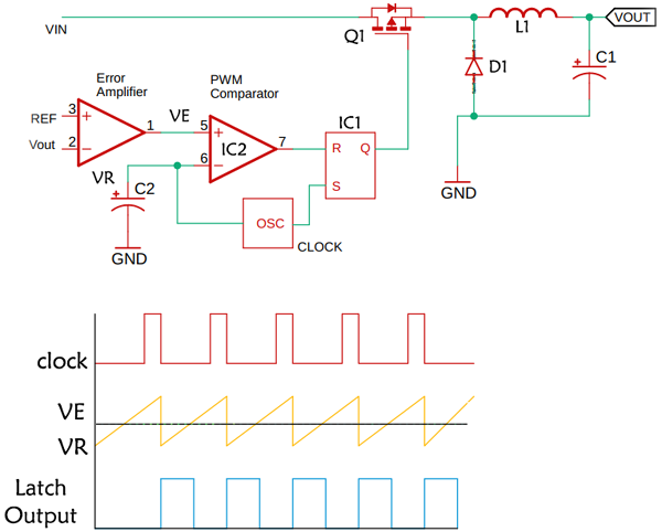
Voltage mode control is the most basic method through which only the output voltage is returned. The feedback voltage is compared with the reference voltage with the help of an error amplifier. As you can see that in the image above, the output of the error amplifier is compared with the PWM generator that uses a triangular wave as its reference voltage. As a result, the pulse of the PWM signal controls the output voltage. This technique is often used because it has some benefits over other controllers. It has a much better noise margin because we are looking at the signal that has a gain stage, and the error amplifier helps to minimize the signal and noise problems. As it is running at a constant switching frequency, we can get a linear dynamic response. The disadvantage of this circuit is that the time involved inside the loop have both inductor and capacitor. In this circuit, the overall bandwidth of the circuit gets relatively low to stay away from the fact that those two components together can give us a 180-degree phase shift that can normally cause instability and that is the purpose of the competition circuit to keep that from happening.
Current Mode Control
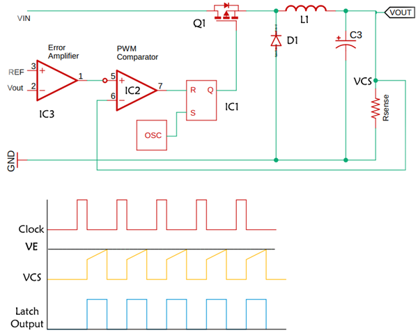
The current mode control is a slight modification of the voltage-mode control topology. It improves the voltage mode controller in a couple of interesting ways, the schematic looks basically the same. We have the same output filter the same power switch. We still have an error amplifier with its reference and a PWM comparator and we also have the oscillator circuit, but the function of this oscillator is only to provide a time base. All it does is to switch on/off the MOSFET at a regular rate with a constant switching frequency. So first, it’s a constant switching frequency algorithm and second, it’s going to be pulse width modulated.
But the trigger that terminates each pulse is not directly from the output but is generated by the ramp of the current waveform in the output inductor and as you see, the signal is going to the PWM comparator is a current sensing signal and it’s the position between the power MOSFET and the input of the inductor. Unlike the voltage mode controller, in a current-mode controller, the inductor current in the circuit is measured and used instead of the triangular waveforms. In many controllers, this process is done by using shunt resistors to measure the current. This mode of control is fairly complex than a voltage mode control because in this mode you have to consider not only the current feedback loop but also the voltage feedback loop. Although the circuit is quite complex, there are many advantages of this circuit over the voltage mode converter. These include a higher stable feedback loop and a fast load transient response than that of voltage mode.
Hysteresis(ripple) Control
Since we are talking about the different types of control topologies, there exists another type of controller that is known as hysteresis or ripple controller. This controller was designed to meet the power demand of very fast switching circuits or circuits that can draw a very large amount of power in a very short period of time such as CPUs, Microcontrollers, FPGA, and GPU. In this method, the output voltage is directly measured and compared with the help of an error amplifier. If the voltage gets below a certain threshold, the output voltage is quickly adjusted by the comparator and the error amplifier.
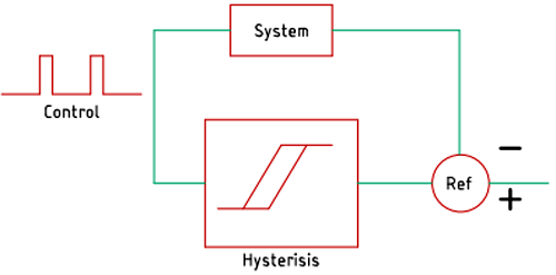
A basic schematic of the hysteresis controller is shown above. It is sometimes known as a bang-bang controller. In this circuit, we have a system and an output comparator that is comparing the output to the reference and it’s producing the difference. So, the output is compared to the reference and fed to the hysteresis comparator that produces the output. In our case, the output will never rest because the output will be always changing between levels once the output reaches the higher value of hysteresis, the control output will go down and the output will drop, and then it will kick again and will continue as an on-off operation. The system here is very typical and there are many different algorithms out there.
