

Analyzing circuit network is a crucial part in designing or working with pre-designed circuits, which deals with current and voltage in each node or branch of circuit network. However, this analyzing process to find out current, voltage or wattage of a node or branch, is a bit complex as lot of components are connected together. Proper analyzing also depends upon the technique we pick for find out current or voltage. The basic analyzing techniques are Mesh Current Analysis and the Nodal Voltage Analysis.
These two techniques follow the different rules and have different limitations. Before going to analyze a circuit in a proper way, it is essential to identify which analysis technique is best suitable in terms of complexity and required time for analysis.
What to use – Mesh Analysis or Nodal Analysis?
The answer is hidden in the fact that how many numbers of voltage or current sources are available in the specific circuit or network. If the targeted circuit network consists of current sources, then the nodal analysis will be less complicated and easier. But, if a circuit has voltage sources then the mesh analysis technique is perfect and takes less calculation time.
In many circuits, both current and voltage sources are available. In those situations, if the number of current sources is larger than the voltage sources, then the nodal analysis is still the best choice and one need to convert the voltage sources to an equivalent current sources.
We previously explained the Mesh Current Analysis, so here in this tutorial, we discuss Nodal Voltage Analysis and how to use it in a circuit network.
Nodal Analysis
As the name suggests, Nodal is came from the term node. Now what is a node?
A circuit may have a different kind of circuit elements, component terminals etc. In a circuit where at least two or more circuit elements or the terminals are joined together is called a node. Nodal analysis is done on nodes.
In the case of Mesh Analysis, there is a limitation that mesh analysis can only be done in planner circuit. Planner circuit is a circuit that can be drawn into the plane surface without any crossover. But for nodal analysis, there is no such kind of limitation, because each node can be assigned a voltage which is an essential parameter to analyze a node using the Node Analysis Method.
In node analysis, the first step is to identify the number nodes exist in a circuit network, whether it is planer circuit or non-planer circuit.
After finding the nodes, as it deals with a voltage, one needs a reference point to assign voltage levels to each node. Why? Because the voltage is a potential difference between two nodes. Therefore, to differentiate, a reference is required. This differentiation is done with a common or shared node which acts as a reference. This reference node needs to be zero to get the perfect voltage level other than the ground reference of a circuit.
So, if a five nodes circuit network has one reference node. Then to solve the remaining four nodes a total of four nodal Equations are needed. In general, to solve a circuit network using nodal analysis technique which has N numbers of total nodes, N-1 number of nodal Equations is needed. If these all are available, it is really easy to solve the circuit network.
Following steps are required to solve a circuit network using Nodal Analysis Technique.
- Finding out nodes in the circuit
- Finding out N-1 equations
- Finding out N-1 voltage
- Applying Kirchhoff's current law or KCL
Finding Voltage in Circuit using Nodal Analysis - Example
To understand the nodal analysis let's consider the below circuit network,
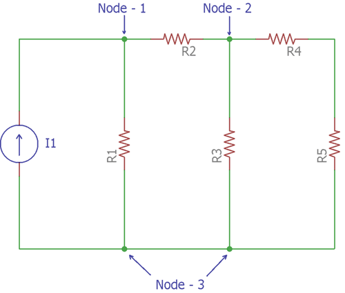
The above circuit is one of the best examples to understand Nodal Analysis. This circuit is pretty simple. There are six circuit elements. I1 is a current source and R1, R2, R3, R4, R5 are five resistors. Let’s consider these five resistors as five resistive loads.
These six component elements have created three nodes. So, as discussed before, the numbers of nodes have been found.
Now, there is N-1 number of nodes that means 3-1 = 2 nodes are available in the circuit.
In the above circuit network, Node-3 is considered as a reference node. That means the voltage of node 3 has a reference voltage of 0V. So, the remaining two nodes, Node-1 and Node-2 need to be assigned a voltage. So the voltage level of Node-1 and Node-2 will be in reference to Node-3.
Now, let's consider the next image where the current flow of each node is shown.
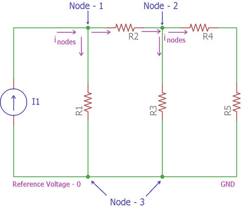
In the above image, Kirchhoff’s current law is applied. The amount of current entering the nodes is equal to the current leaving from the nodes. The arrows indicated the flow of currents Inodes in both Node-1 and Node-2. The circuit’s current source is I1.
For the Node-1, the amount of current entering is I1, and the amount of current leaving is the sum of current across R1 and R2.
Using Ohms law, the current of R1 is (V1 / R1) and the current of R2 is ((V1 – V2) / R2).
So, applying Kirchoff's law, The Node-1 equation is
I1= V1/R1+ (V1 - V2)/R2 …… [Equation:1]
For the Node-2 the currents through R2 is (V1 - V2)/R2, current through R3 is V2 / R3 and the resistor R4 and R5 can be combined to achieve a single resistance which is R4 + R5, the current through these two resistors will be V2/(R4 + R5).
Therefore, applying Kirchoff's current law, the equation of Node-2 can be formed as
(V2-V1 )/R2+ V2/R3+ V2/(R4 + R5)=0………………[Equation:2]
By solving these two equations, voltages at each node can be found without any further complexity.
Example of Nodal Voltage Analysis
Let's see a practical example-
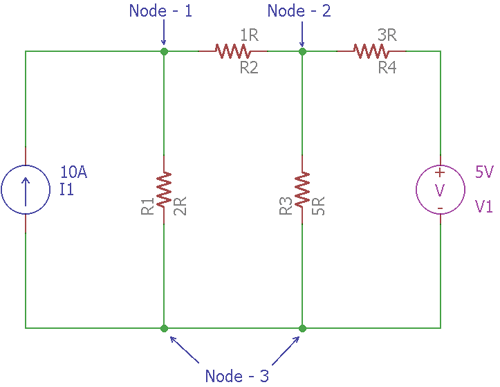
In the above circuit, 4 resistive loads create 3 Nodes. The Node-3 is the reference node which has a potential voltage of 0V. There is one current source, I1, which is providing 10A of current and one voltage source which is providing 5V voltage.
To solve this circuit and finding out the current in each branch, Node analysis method will be used. During the analysis, as there are two remaining nodes, 2 separate node equations are required.
For the Node-1, as per Kirchhoff’s current law and Ohms Law,
I1= VR1+ (V1- V2)/R2
Therefore, by providing the exact value,
10 = V1 / 2 + (V1 - V2) / 1 or, 20 = 3V1 - 2V2…….[Equation:1]
Same for Node-2
(V2 - V1) / R2 + V2/ R3 + V2 / (R4) = 0 or,
(V2 - V1) / 1+ V2 / 5+  (V2 - 5) / 3 = 0 or,
15V2 - 15V1 + 3V2 + 5V2 - 25=0
-15V1+ 23V2 = 25 ………………. [Equation: 2]
By solving two equations, we get the value of V1 is 13.08V and value of V2 is 9.61V.
The circuit further constructed and simulated in PSpice to verify the calculated results with simulated results. And we got the same results as calculated above, check the simulated results in the picture below:
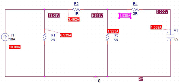
So this is how voltage at different nodes of the circuit can be calculated using Nodal Voltage Analysis.
