

There have been many development boards recently built around the ESP32-S3. Most development boards come with a display, some also include cameras and buttons, and a few have speakers and microphones. Finding one that brings all these components together without compromising on quality has been the real challenge for makers and developers. Keeping all this in mind, we found a dev board that brings everything together in one module, the Adafruit MEMENTO.
CircuitDigest presents the Smart Home & Wearables Project Contest 2025! Win exciting prizes worth up to ₹7,00,000 and receive free development boards through our partnership with DigiKey. For registration, dive into contest details.
This Adafruit MEMENTO tutorial provides complete guidance for both Adafruit MEMENTO Arduino and Adafruit MEMENTO Python programmable workflows using CircuitPython.With all these features, it makes a perfect choice for our upcoming Smart Home and Wearable Project Challenge, where you can win prizes of up to Rs. 7,00,000. You can also win a development board and some cool goodies just by sharing your project ideas. So don’t forget to check out the Smart Home and Wearable Project Challenge for more details.
Nonetheless, it's been difficult for makers and developers to find an Adafruit MEMENTO camera board that employs high-quality components without sacrificing quality. The Adafruit MEMENTO dev board provides a solution by housing a 5MP auto-focus camera, colour display, audio, and a plentiful amount of I/O with one stylish board. If you are doing Adafruit MEMENTO projects for the Internet of Things (IoT), doing computer vision experiments, or making art installations, this guide will explore everything from hardware pinouts to programming the Adafruit MEMENTO dev board. The Adafruit MEMENTO software ecosystem is designed to be utilised by everyone, from complete beginners to experienced software developers.
So, without waiting any longer, let’s dive into the actual development board.
What's Inside the Adafruit MEMENTO Package?
This package is quite simple, containing just one main Adafruit MEMENTO dev board. This package is quite simple, containing just one main Memento Dev Board. You can see the unboxing image below.
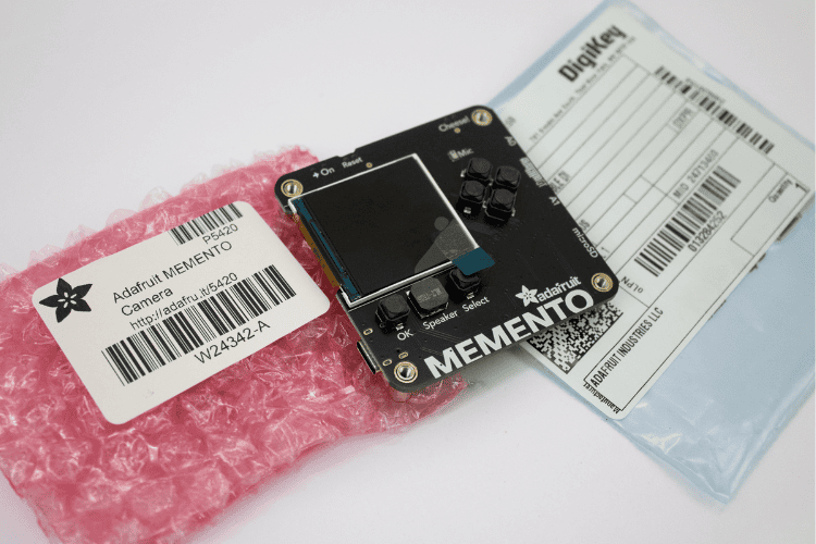
The board has scratch protection for its camera and display, along with four screw inserts at each corner. The PCB has a square design, placing the display, microphone, speaker, and some buttons on the front side, while the camera, SD card slot, all I/O connections, and an accelerometer are on the back. The boot and restart buttons, along with the Type-C input, are placed on the sides for easy access. All the components have been positioned with practicality in mind. Without a doubt, this board is perfectly made in every way. That was my first impression. Next, let’s take a detailed look at the features of this module.
Features of the Adafruit MEMENTO
The Adafruit MEMENTO camera board integrates professional-grade components into a compact development platform, making it ideal for IoT projects, photography applications, and computer vision experiments. To make this board outstanding and usable for most applications, it comes packed with a rich set of features:
| Feature | Description |
| ESP32-S3 module with 4 MB Flash, 2 MB PSRAM | Dual-core 240MHz Tensilica with Wi-Fi and BTLE. |
| OV5640 camera module with 72° field of view and auto-focus motor | 5MP camera sensor with a built-in JPEG encoder. |
| 1.54" 240x240 Color TFT | For previewing camera images or designing a user interface. |
| MicroSD card slot | Store images or animations on any SPI-capable microSD card. Note: Supports cards up to 32GB capacity. |
| Two Digital/Analog Stemma Ports | JST PH-3 connectors for A0, A1, and power+ground, allowing external buttons, LEDs, or sensors. Can provide 3V or 5V power. |
| I2C Stemma QT Port | Connect almost any I2C sensor with a Stemma QT JST SH port, providing 3.3V power and logic. |
| LIS3DH Accelerometer | A triple-axis accelerometer for detecting orientation, shaking, or movement. |
| LiPoly battery charging support | Works with a 3.7/4.2V 350mA or 420mA battery for on-the-go snaps. |
| 6 User Buttons | Change modes, preview saved images, or even play DOOM (?). Connected through a GPIO expander. |
| Buzzer | Play tones or alerts, or indicate when a photo is successfully taken. |
| Analog Microphone | Can be used as a sensor to detect loud sounds (not for recording video with audio). |
| Shutter/Boot button | Connected to GPIO 0 for entering the ROM bootloader. |
| Reset button | For entering the bootloader or restarting the board. |
| On/Off switch | Cuts all power when using a battery. |
| USB Type-C | For programming the ESP32-S3, REPL access in CircuitPython, and charging the optional LiPoly battery. |
| Breakout pads for hardware UART | For deeper debugging needs, solder wires to the through-hole pads to connect to a console cable. |
| Four M3 standoffs | For mounting or attaching to an enclosure. |
On the software side, it can be programmed with both Arduino IDE and CircuitPython. Between CircuitPython and Arduino IDE, CircuitPython is definitely the easier one for coding and interfacing, making the board truly Python programmable for educational and rapid prototyping purposes.
Adafruit MEMENTO Projects: Real-World Applications
The versatility of the Adafruit MEMENTO camera board makes it suitable for numerous applications across different domains. Below are practical Adafruit MEMENTO projects you can build using either Adafruit MEMENTO Arduino or CircuitPython programming:
| Application | Description |
| Photography: | Digital photos, timelapse, custom effects and filters |
| Security: | Motion detection, surveillance systems, automated monitoring |
| IoT Projects: | Wireless camera control, remote photo capture, smart home integration |
| Education: | Learning programming with CircuitPython/Arduino, computer vision experiments |
| Creative Arts: | Interactive photo booths, art installations, custom camera apps |
| Development: | Prototyping vision applications, testing camera algorithms |
| Automation: | Scheduled photography, event-triggered image capture |
| Portable Projects: | Handheld camera systems, field research documentation |
| Remote Control: | Wireless operation via TouchOSC or custom interfaces |
| Data Collection: | Scientific imaging, environmental monitoring, research projects |
A practical Adafruit MEMENTO project combining 3D printing with IoT integration demonstrates the board's capabilities.
Adafruit MEMENTO Pinout Guide: Complete Hardware Overview
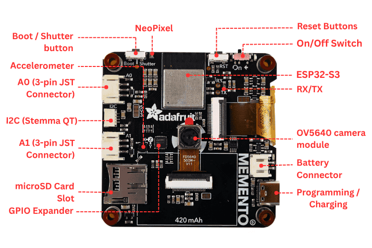
Now that you know more about the features of the MEMENTO, let's move to the physical overview, where we take a look at the overall hardware and its pinouts in detail.
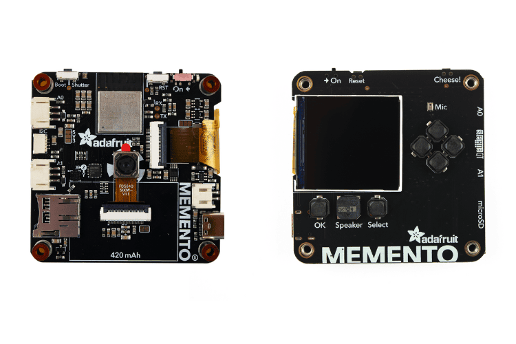
Above, you can see the front and back images of the MEMENTO showcasing the comprehensive component layout that makes this board ideal for Adafruit MEMENTO projects.
LCD Display Specifications & Pin Configuration
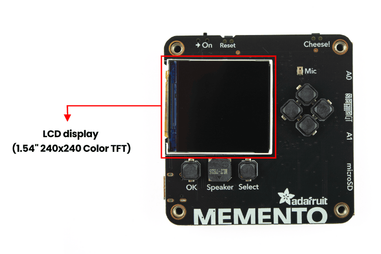
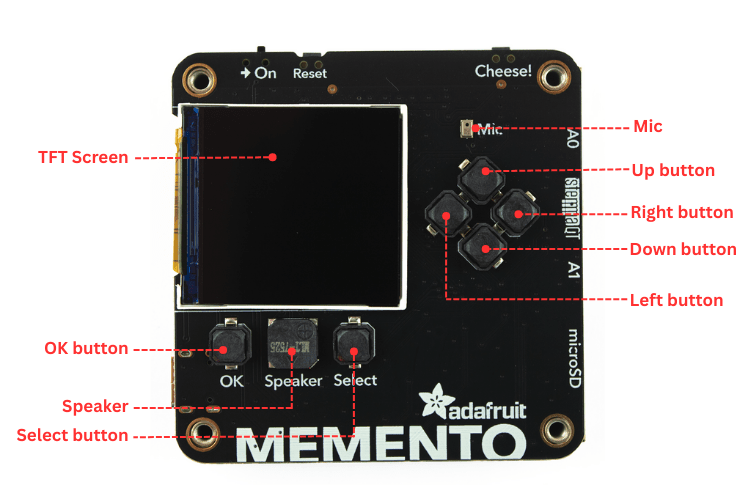
On the front side of the MEMENTO, the LCD (1.54" 240x240 Colour TFT) takes up most of the space. This is useful for previewing camera images or creating your own user interface design. It uses the ST7789 driver, which is supported by both Arduino and CircuitPython.
It uses the following pins for communication:
| Pin | GPIO | CircuitPython Access | Arduino Access |
| MOSI | GPIO35 | board.MOSI | MOSI |
| SCK | GPIO36 | board.SCK | SCK |
| MISO | GPIO37 | board.MISO | MISO |
| DC | GPIO40 | board.TFT_DC | TFT_DC |
| CS | GPIO39 | board.TFT_CS | TFT_CS |
| Backlight | GPIO45 | board.TFT_BACKLIGHT | TFT_BACKLIGHT. |
| Reset | GPIO38. | board.TFT_RESET | TFT_RESET or TFT_RST. |
User Interface Buttons & GPIO Expander Setup
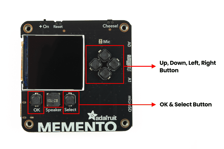
There are a total of six buttons for the user interface in the Adafruit MEMENTO dev board. There are a total of six buttons for the user interface. These buttons are more than enough for most designs. One thing to note is that these buttons are not directly connected to the ESP32-S3. Instead, they use the AW9523 GPIO Expander. The pin mapping is:
| Button | Pin |
| OK button | pin 11 |
| Select button | pin 1 |
| Up button | pin 13 |
| Down button | pin 15 |
| Left button | pin 14 |
| Right button | pin 12 |
Both the Arduino and CircuitPython PyCamera libraries have built-in support for these buttons, making them easy to use in Adafruit MEMENTO Arduino and CircuitPython projects.
Microphone & Speaker Configuration
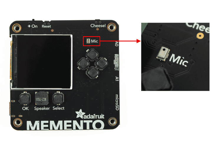
On the front side of the Adafruit MEMENTO camera board, above the four user buttons, is the analog MEMS microphone, labelled Mic on the board’s silkscreen. It can be used as a sensor to detect loud sounds for various Adafruit MEMENTO projects. It is not intended for recording video with audio.
The analog input from the microphone is connected to GPIO2. It’s accessible in CircuitPython with the board. MIC and in Arduino with 2. This component enables audio feedback in your Adafruit MEMENTO software applications.
ESP32-S3 Module: The Core Processor
Now, looking at the back side, you'll find the hero of the Adafruit MEMENTO dev board: the Espressif ESP32-S3 with 3.3V logic/power. It has 4MB of Flash and 2MB of PSRAM. This MCU comes with Wi-Fi and BLE, making IoT-related tasks much easier for Adafruit MEMENTO projects.
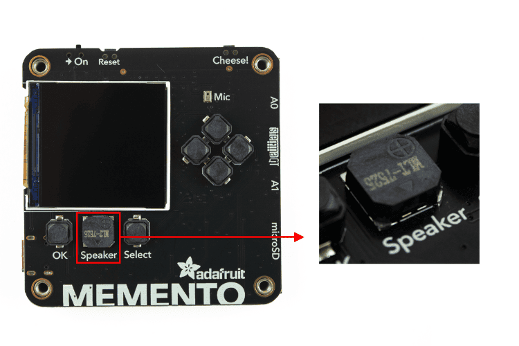
Below the TFT display, between two of the user buttons, is the speaker, also labelled Speaker in the silkscreen.
The output from the speaker is connected to GPIO46. It’s accessible in CircuitPython with the board.SPEAKER and in Arduino with SPEAKER.
Note: The speaker is muted via pin 0 on the AW9523 GPIO expander, so don’t forget to unmute it before expecting any sound!
Camera Module: OV5640 with Auto-Focus
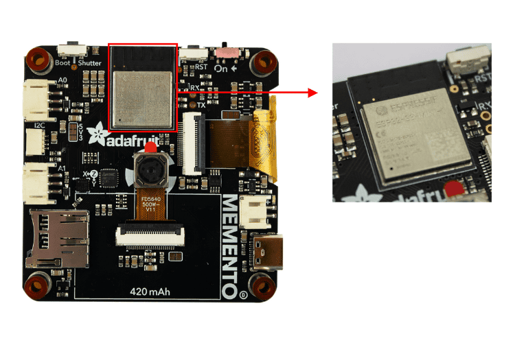
Now, looking at the back side, you’ll find the hero of the dev board: the Espressif ESP32-S3 with 3.3V logic/power. It has 4MB of Flash and 2MB of PSRAM. This MCU comes with Wi-Fi and BLE, making IoT-related tasks much easier.
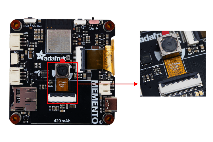
Next, of course, our attention moves toward the camera module at the center of the board. Unlike other ESP32-CAM modules, this is no ordinary camera. It has a built-in motor that enables the auto-focus feature, making it perfect for professional Adafruit MEMENTO projects. And yes, it’s a 5MP sensor with a 72° field of view.
Below the camera connector, there is a jumper to provide 3.3V to the auto-focus motor. You can cut the jumper to disconnect DATA1 from 3.3V and disable auto-focus.
The camera uses the following pins for Adafruit MEMENTO dev board programming:
| VSYNC | GPIO5. Accessible in CircuitPython with board.CAMERA_VSYNC and in Arduino with VSYNC_GPIO_NUM. |
| HREF | GPIO6. Accessible in CircuitPython with board.CAMERA_HREF and in Arduino with HREF_GPIO_NUM. |
| XCLK | GPIO8. Accessible in CircuitPython with board.CAMERA_XCLK and in Arduino with XCLK_GPIO_NUM. |
| PCLK |
GPIO11. Accessible in CircuitPython with board.CAMERA_PCLK and in Arduino with PCLK_GPIO_NUM. |
| PWDN | GPIO21. Accessible in CircuitPython with board.CAMERA_PWDN and in Arduino with PWDN_GPIO_NUM. |
| DATA2 | GPIO13. Accessible in CircuitPython with board.CAMERA_DATA2 and in Arduino with Y2_GPIO_NUM. |
| DATA3 | GPIO15. Accessible in CircuitPython with board.CAMERA_DATA3 and in Arduino with Y3_GPIO_NUM. |
| DATA4 | GPIO16. Accessible in CircuitPython with board.CAMERA_DATA4 and in Arduino with Y4_GPIO_NUM. |
| DATA5 | GPIO14. Accessible in CircuitPython with board.CAMERA_DATA5 and in Arduino with Y5_GPIO_NUM. |
| DATA6 | GPIO12. Accessible in CircuitPython with board.CAMERA_DATA6 and in Arduino with Y6_GPIO_NUM. |
| DATA7 |
GPIO10. Accessible in CircuitPython with board.CAMERA_DATA7 and in Arduino with Y7_GPIO_NUM. |
| DATA8 | GPIO9. Accessible in CircuitPython with board.CAMERA_DATA8 and in Arduino with Y8_GPIO_NUM. |
| DATA9 | GPIO7. Accessible in CircuitPython with board.CAMERA_DATA9 and in Arduino with Y9_GPIO_NUM. |
| RESET | GPIO47. Accessible in CircuitPython with board.CAMERA_RESET and in Arduino with RESET_GPIO_NUM. |
We already know there's a heavy demand for the peripherals we've seen above, so the Adafruit MEMENTO camera board includes the AW9523 GPIO Expander IC to provide additional GPIO pins. You can spot this IC near the camera, specifically to the left of the camera module.
The I2C address of the GPIO expander (AW9523) is 0x58.
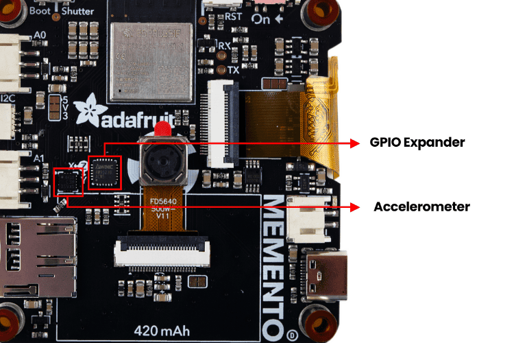
Near the AW9523, there is a LIS3DH Accelerometer. It’s a triple-axis accelerometer that can detect orientation, shaking, or movement for motion-sensitive Adafruit MEMENTO projects. It communicates over I2C at address 0x19. Its interrupt (IRQ) pin is connected to GPIO3, which is accessible in CircuitPython with the board.IRQ and in Arduino with 3.
Storage & Expansion: SD Card and Stemma Ports
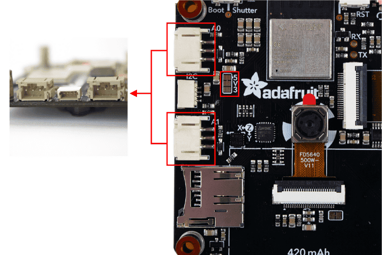
For user I/O in Adafruit MEMENTO dev board programming, there are two JST-PH connectors on the left side of the board, labelled A0 and A1. These are 3-pin JST connectors that can be used for sensors, NeoPixels, or analog input/output.
-
A0 is connected to GPIO17 (accessible in CircuitPython with board.A0 and in Arduino with A0).
-
A1 is connected to GPIO18 (accessible in CircuitPython with board.A1 and in Arduino with A1).
You don’t need to worry about voltage on these pins, as they can be configured to either 3.3V or 5V. By default, they provide 5V. Between the two connectors is a jumper labelled 5V3. This jumper can be cut and re-soldered to switch the VCC signal from 5V to 3V.
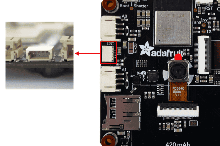
Between A0 and A1, you’ll find a tiny connector labelled I2C on the silkscreen. This is a 4-pin Stemma QT connector perfect for connecting additional sensors to your Adafruit MEMENTO projects. The I2C lines have pull-ups to 3.3V.
- SDA – GPIO34
- SCL – GPIO33
In an Arduino, you can use this connector with a wire. In CircuitPython, you can use it with a board.SCL, board.SDA, board.I2C(), or board.STEMMA_I2C().
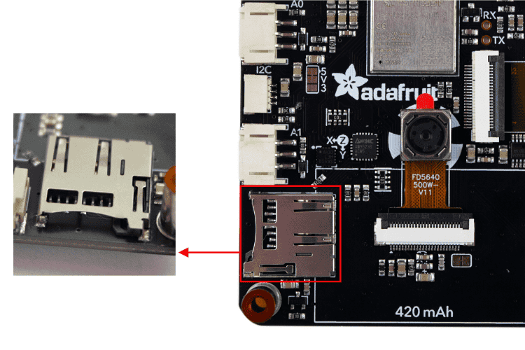
Towards the bottom-left corner on the back of the MEMENTO is the microSD card slot. It can be used to store images or animations on any SPI-capable microSD card, essential for most Adafruit MEMENTO camera board applications.
- SDCS (chip select pin) – connected to GPIO48. Accessible in CircuitPython with the board.CARD_CS and in Arduino with SD_CS or SD_CHIP_SELECT.
- SDCD (card detect pin) – connected to pin 9 on the AW9523.
Power Management & Battery Support
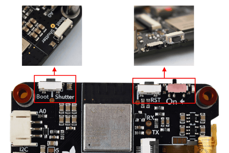
Along the top edge of the board are two buttons:
- The Boot button, labelled Boot and Shutter on the silkscreen, is connected to GPIO0. Accessible in CircuitPython with the board.BUTTON and in Arduino with SHUTTER_BUTTON. Hold it while pressing reset to enter ROM bootloader mode for Adafruit MEMENTO dev board programming.
- The Reset button, labelled RST on the silkscreen, is connected to the ESP32-S3 reset pin. Press once to restart your firmware, or press again after about half a second to enter bootloader mode.
To the right of the boot button is the NeoPixel. This addressable RGB LED works as a status LED (in CircuitPython and the bootloader) and can also be controlled with code in the Adafruit MEMENTO software. It’s connected to GPIO1, accessible in CircuitPython with board. NEOPIXEL and in an Arduino with PIN_NEOPIXEL or NEOPIXEL_PIN.
On the top-right edge of the board is the On/Off switch, labelled On on the silkscreen. This sliding switch cuts all power to the board, essential for portable Adafruit MEMENTO projects.
To the right of the switch is the power LED, a green LED that lights up whenever the board has power.
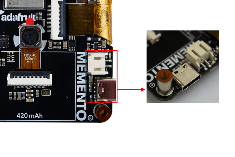
| USB-C port | Used for both powering and programming the board. Any USB-C cable will work. When plugged in, it also charges the LiPoly battery. |
| LiPoly connector/charger | A JST 2-PH port for plugging in any 350mAh or larger 3.7/4.2V LiPoly battery. The MEMENTO can run from the battery and charge it while USB is plugged in. The board silkscreen includes an outline sized perfectly for the 420mAh battery available in the shop. |
| Battery Monitor Pin | Monitor battery percentage via an ADC pin, accessible in CircuitPython with board.BATTERY_MONITOR and in Arduino with BATT_MONITOR. |
| Power Selection Jumper | Located above the TFT display ribbon cable. It selects whether the 2.8V supply is powered from 3.3V or 5V. You can cut and re-solder it to switch to 5V. |
With this, we’ve completed the physical overview of the Adafruit MEMENTO camera board. Next, to make using the MEMENTO simpler, we’ll look at some official resources to get started with your Adafruit MEMENTO projects.
Official Adafruit MEMENTO Resources & Documentation
Unlike other Adafruit modules, this Adafruit MEMENTO dev board is also perfectly documented to get started. You can begin by referring to the Adafruit MEMENTO Camera Board.
In this comprehensive Adafruit MEMENTO tutorial, you will find: Overview, Pinouts, Installing CircuitPython, microSD Card Formatting, Notes, CircuitPython MEMENTO Starter Projects, Frames to GIFs, Arduino IDE Setup, Arduino MEMENTO Library Installation and Starter Projects, Factory Reset, and Downloads.
Hopefully, these resources will be all you need for Adafruit MEMENTO dev board programming. Next, let’s do a quick exploration of Memento using the Arduino IDE. If you wish, you can also go with CircuitPython for a more Python-programmable experience.
Adafruit MEMENTO Arduino Tutorial: Complete Setup Guide
With a dedicated board selection and library already available for this module, the first test program is quite simple.
Programming the Adafruit MEMENTO dev board using the Arduino IDE will allow you to take advantage of the vast libraries and community resources that support Arduino projects. This Adafruit MEMENTO tutorial will guide you through the complete setup for MEMENTO dev board programming using Arduino's familiar development environment.
Setting Up
There are three primary steps needed to set up the Arduino environment:
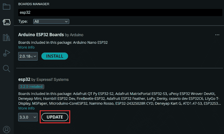
⇒ Step 1: Installing ESP32 Board Support for Adafruit MEMENTO
The first step in Adafruit MEMENTO dev board programming requires updating the ESP32 board library to ensure compatibility with the ESP32-S3 processor and all MEMENTO features.
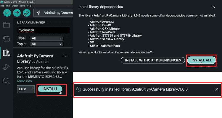
⇒ Step 2: Installing Adafruit MEMENTO Software Libraries. The Adafruit MEMENTO software ecosystem includes specialised libraries that simplify camera control, display management, and hardware interfacing. along with all dependencies. Even if you already have most of them installed, enabling this option will update the existing ones or install the missing ones.
⇒ Step 3: Understanding the Example Sketches
The Adafruit MEMENTO Arduino library includes two comprehensive example programs demonstrating core functionality. Access these examples through File → Examples → Adafruit PyCamera.
Once installed, navigate to the Examples folder. You’ll find two sketches:
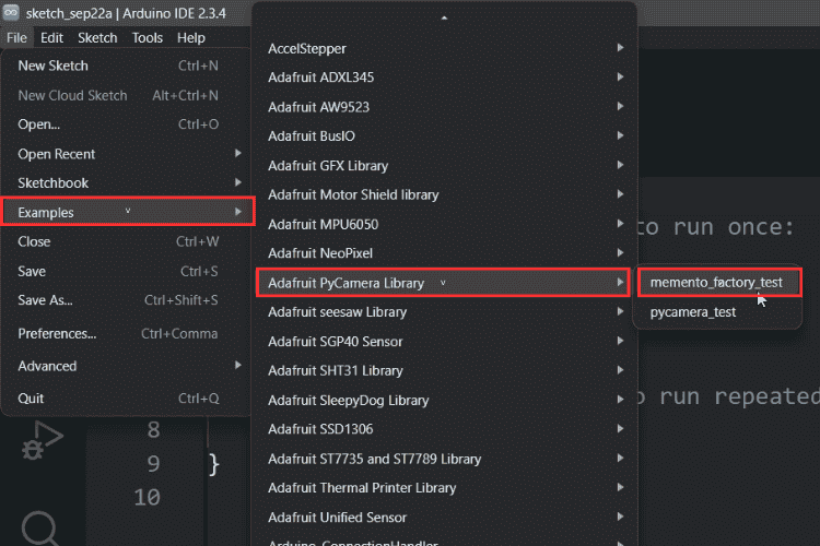
Differences Between Pycamera_test and Memento_factory_test,
| Analog readings: | Pycamera_test reads both A0 and A1, while Memento_factory_test only reads A0. |
| OK button: | Does nothing in Pycamera_test; cycles through ring light colors in Memento_factory_test. |
| SEL button: | Does nothing in Pycamera_test; adjusts ring light brightness in Memento_factory_test. |
| Ring light control: | Not present in Pycamera_test; fully implemented in Memento_factory_test. |
| Interrupt handling: | Missing in Pycamera_test; IRQ pin 3 interrupt added in Memento_factory_test. |
| Ring light variables: | Absent in Pycamera_test; includes color array and brightness control in Memento_factory_test. |
Proper board selection is critical for successful Adafruit MEMENTO dev board programming. If you have it, you can use these extra features. Otherwise, both examples provide the same basic camera functions, but Memento_factory_test includes extra testing features.
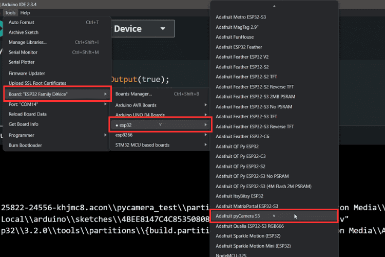
⇒ Step 4: Connecting and Selecting the Adafruit MEMENTO Board
Proper board selection is critical for successful Adafruit MEMENTO dev board programming.
- Connect the MEMENTO Dev Board to your PC.
- Hold the Boot button and press the Reset button once. This puts the board into upload mode.
- In Arduino IDE, select:
Board → ESP32 → Adafruit PyCamera S3
Now, click Compile and Upload. The code will be uploaded to your MEMENTO board.
Using the PyCamera
The Adafruit MEMENTO software includes comprehensive camera control features accessible through the built-in buttons and programmable through code. Understanding the PyCamera interface is essential for developing custom Adafruit MEMENTO projects.
By default, the captured image won’t be stored unless you insert an SD card.
Note: The Adafruit MEMENTO Arduino library supports both FAT16 and FAT32 filesystems, providing compatibility with cards up to 32GB capacity.
Once the SD card is inserted, you can take pictures by pressing the Shutter button at the top right.
And there are two extra features,
Colour Filter Effects
These filters are useful for artistic Adafruit MEMENTO projects, security applications requiring specific visual modes, or creative photography experiments:
Colour Filters – Use the Left and Right buttons to cycle through filters:
- Normal/None
- Black & White
- Sepia
- Negative
- Greenish
- Reddish
- Bluish
The example programs demonstrate the Adafruit MEMENTO camera board's capabilities through intuitive button controls
The OV5640 camera sensor supports multiple resolution modes, allowing you to balance image quality against storage space and processing speed in your Adafruit MEMENTO projects.
Resolution Adjustment – Use the Up and Down buttons to change image resolution. Available options:
| QQVGA: | 160×120 |
| QVGA: | 320×240 |
| HVGA: | 480×320 |
| VGA: | 640×480 |
| SVGA: | 800×600 |
| XGA: | 1024×768 |
| HD: | 1280×720 |
| SXGA: | 1280×1024 |
| UXGA: | 1600×1200 |
| QXGA: | 2048×1536 |
| QSXGA: | 2560×1920 |
The resolution of the images can be adjusted in real time.
This Adafruit MEMENTO tutorial has been created through hands-on testing and verification of all features, pinouts, and programming procedures.
This rich Adafruit MEMENTO tutorial has taken you from hardware specifications and pinout details to getting started programming the Adafruit MEMENTO dev board using the Arduino IDE. Whether you choose to begin with Adafruit MEMENTO Arduino development or the Adafruit MEMENTO programmable CircuitPython environment, this versatile camera board has professional features in a convenient package.
The combination of the ESP32-S3 processor, 5MP auto-focus camera, colour display, and rich connectivity makes the MEMENTO dev board a great choice for limitless Adafruit MEMENTO projects, from simple learning projects to sophisticated Internet of Things (IoT) camera systems. It is the reliability of the Adafruit MEMENTO software ecosystem, supported by extensive documentation and community support, that means your projects can begin quickly and smoothly scale in complexity. You could create security systems, wildlife cameras, time-lapse devices, or interactive art installations, and the Adafruit MEMENTO development board is a great place to start. Download the example code and explore the Adafruit MEMENTO software features, and you will be able to bring your vision to life in this powerful, well-documented development platform.
After a deep dive into the Adafruit MEMENTO, it's clear why we chose this board for this year's contest. It's not just another ESP32 camera module-it’s a way to combine your creativity and skills into a fun project. This article gives you a basic idea of its features, and we can’t wait to see your innovative ideas for this year’s contest!
To help you get going, check out this sample project: IoT Window Bird Feeder with Camera. This project uses 3D printing along with IoT on Adafruit IO, making it a great source of inspiration.
