

Note: This tutorial was written after Arduino has officially launched its support for ESP32 boards. So if you have followed the old method of using GIT to install the boards then you would have to follow these steps again (highly recommended) if you need support for new libraries. If you are working with ESP32 for first time you do not have to worry about this.
Internet has reached almost every pocket through smart phones, it is estimated that about 3.2 billion people use internet but surprisingly about 8.4 billion devices use internet. That is electronics devices are connected to internet more than twice of the population who use internet and it is making the things around us smarter every day. The major reason is the boom of Internet of things which is commonly known as IOT, it is also estimated that by the end of 2020 we will have 20.4 billion devices connected to the internet. So it’s time to gear up and rise up our sleeves to work with IOT projects if we want to keep up with this development, lucky for us the open source platforms like Arduino and Espressif Systems has made things a lot easy for us.
Espressif Systems launched the ESP8266-01 long back which opened doors to many hobbyists to get into the world of IOT, since then the community has been developing strongly and many products has hit the market. Now the launch of ESP32 Espressif has taken things to a new level. This tiny cheap 8$ module is a dual core 32-bit CPU with built in Wi-Fi and dual-mode Bluetooth with sufficient amount of 30 I/O pins for all basic electronics projects. All these features are very easy to use, since it can be programmed directly from the Arduino IDE. Exiting enough... So let’s start programming ESP32 with Arduino IDE and then you can try all the interesting IoT based projects using ESP32.
Materials Required:
- ESP32 Module
- Arduino IDE
- Programming cable (micro USB cable)
- The soul stone from MCU (just kidding)
Hardware Information of ESP32:
Let’s take a look the ESP32 module. It is slightly bigger than the ESP8266-01 module and is breadboard friendly since most of the pin headers are broken out as I/O pins facing each other which is a great thing. Let’s break the board into small parts to know the purpose of each segment
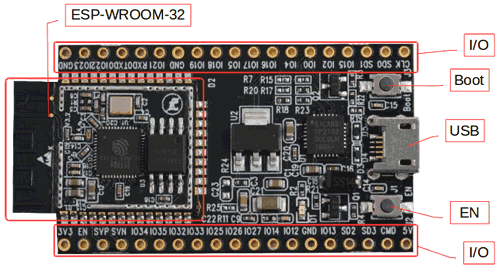
As you can see the heart of the module is the ESP-WROOM-32 which is a 32-bit microprocessor. It also has a couple of buttons and LEDs which are explained below.
Micro-USB jack: The micro USB jack is used to connect the ESP32 to our computer through a USB cable. It is used to program the ESP module as well as can be used for serial debugging as it supports serial communication
EN Button: The EN button is the reset button of the ESP module. Pressing this button will reset the code running on the ESP module
Boot Button: This button is used to upload the Program from Arduino to the ESP module. It has to be pressed after clicking on the upload icon on the Arduino IDE. When the Boot button is pressed along with the EN button, ESP enters into firmware uploading mode. Do not play with this mode unless you know what you are doing.
Red LED: The Red LED on the board is used to indicate the power supply. It glows red when the board is powered.
Blue LED: The Blue LED on the board is connected to the GPIO pin. It can be turned on or off through programming. In some Chinese cloned boards like mine, this led might also be in red colour.
I/O pins: This is where major development has taken place. Unlike ESP8266, on ESP32 we can access all the I/O pin of the module through the break-out pins. These pins are capable of Digital Read/Write, Analog Read/Write, PWM, IIC, SPI, DAC and much more. We will get more into that later. But if you are interested you can learn through the pin description at ESP32 Datasheet.
ESP-WROOM-32: This is the heart of the ESP32 module. It is a 32-bit microprocessor developed by Espressif systems. If you are more of a technical person you can read through the ESP-WROOM-32 Datasheet. I have also listed few important parameters below.
|
ESP32 |
|
|
Specification |
Value |
|
Number of cores |
2 |
|
Architecture |
32 bit |
|
CPU Frequency |
|
|
Wi-Fi |
YES |
|
Bluetooth |
YES |
|
RAM |
512 KB |
|
FLASH |
16 MB |
|
GPIO Pins |
36 |
|
Communication Protocols |
SPI, IIC, I2S, UART, CAN |
|
ADC channels |
18 channels |
|
ADC Resolution |
12-bit |
|
DAC channels |
2 |
|
DAC Resolution |
8-bit |
For now this is all the information that we need to know about the hardware. We will cover more in depth as we move with different projects using the ESP32.
Removing the Old Version of ESP32 Board
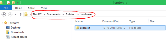
This step can be skipped by users who are using ESP32 with Arduino for the first time. For others who have already installed ESP32 board on Arduino using GIT have to delete the Espriff folder from Arduino Directory.
Windows users can find this folder at Documents/Arduino/hardware, just find the folder and delete it permanently before you proceed with other steps.
Preparing your Arduino IDE
STEP 1: Now, let’s get started. The first step would be to download and install the Arduino IDE. This can be done easily by following the link https://www.arduino.cc/en/Main/Software and downloading the IDE for free. If you already have one make sure it is of the latest version.
STEP 2: Once installed, open the Arduino IDE and go to Files -> Preferences to open the preferences window and locate the “Additional Boards Manager URLs:” as shown below
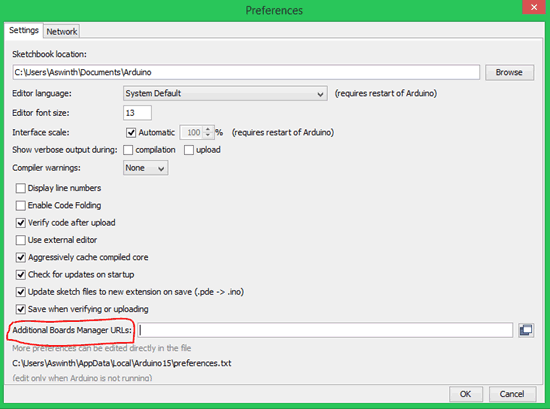
STEP 3: This text box might be empty or might also contain some other URL if you have used it previously for ESP8266. If it is empty simply paste the below URL into the text box
https://dl.espressif.com/dl/package_esp32_index.json
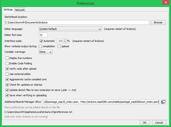
If the text box already contains some other URL just add this URL to it, separate both with a comma (,). Mine already had the ESP8266 URL I just added this URL to and added a comma, like this
https://dl.espressif.com/dl/package_esp32_index.json,
http://arduino.esp8266.com/stable/package_esp8266com_index.json
Once done, my preferences windows looked like this below. Just click on OK and the window will disappear.
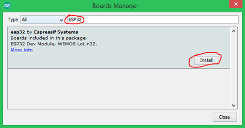
STEP 4: Now go to Tools -> Boards -> Board Managers to open the Board manager window and search for ESP32. If the URL was pasted correctly your window should find the below screen with Install button, just click on the Install button and your board should get installed.
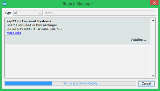
STEP 5: Make sure you have an active internet connection and wait while the installation gets complete. It may take few minutes based on the speed of your internet connection.
That is it now our Arduino IDE is prepared to work with ESP32. Let’s go ahead and check if it is working.
Programming ESP32 with Arduino IDE:
STEP 1: Connect your ESP32 board to your computer through the micro-USB cable. Make sure the red LED goes high on the module to ensure power supply.
STEP 2: Start the Arduino IDE and navigate to Tools -> Boards and select ESP32Dev board as shown below

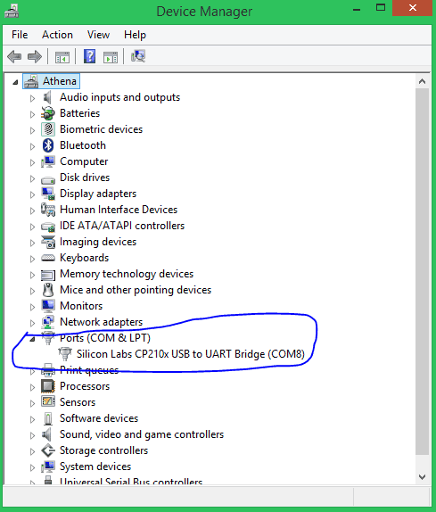
STEP 3: Open device manager and check to which com port your ESP32 is connected to. Mine is connected to COM 8 as shown below
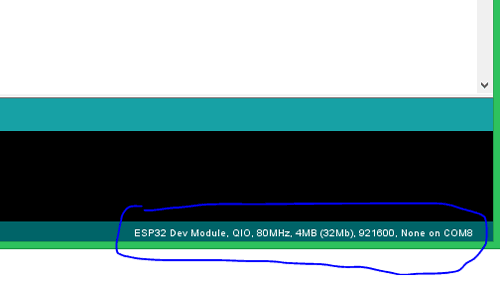
STEP 4: Go back to Arduino IDE and under Tools -> Port select the Port to which your ESP is connected to. Once selected you should see something like this on the bottom left corner of the IDE.
STEP 5: Let’s upload the Blink Program, to check if we are able to program our ESP32 module. This program should blink the LED at an interval of 1 second.
int LED_BUILTIN = 2;
void setup() {
pinMode (LED_BUILTIN, OUTPUT);
}
void loop() {
digitalWrite(LED_BUILTIN, HIGH);
delay(1000);
digitalWrite(LED_BUILTIN, LOW);
delay(1000);
}
The program is very similar to the Arduino blink code hence I am not explain them in detail. But one change is that, here in ESP32 the LED on board is connected to pin number 2, while for Arduino it will be connected to pin number 13.
STEP 6: To upload the code, just click on upload and you should see the Arduino console displaying the following if everything works as expected.
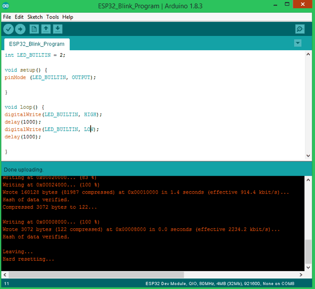
Note: For some modules, you might have to hold the Boot button during uploading to avoid error.
That is it we have successfully uploaded out first code to our ESP32 board. My module with its LED blinking is shown below

This is how Programming ESP32 using Arduino IDE can be implemented. You can go ahead and try the other example programs which are available at File -> Example -> ESP32 to work with other functionalities of the ESP32. If you have had any problem in getting this work, feel free to post the query on the comment sections below. You can also use the Forum for getting technical help.
Complete Project Code
int LED_BUILTIN = 2;

void setup() {

pinMode (LED_BUILTIN, OUTPUT);

}

void loop() {

digitalWrite(LED_BUILTIN, HIGH);

delay(1000);

digitalWrite(LED_BUILTIN, LOW);

delay(1000);

}
Comments
Thank you very much ...Please post this info to Instructables ...I have the esp32 wrover kit which is a very good board as it has all the i/o lines broken out and it has a RGB led ,card slot ,power supply set up for external or usb ,the wrover board built in and a tft lcd built on board so you do not have to buy all that seperate and now it works with the arduino ide wow....THANKS
Thank you very much
I m fresher in iot so can u teach me how to programming for 8channel relay?
its quite simple lets take example if you want to use 3 realy channel from 8 channel relay then try below code in arduino IDE.
int relay = 1;
int realy1 = 3;
int realy2 = 4;
int relay3 = 5;
void setup (){
pinMode(relay1,OUTPUT);
pinMode(relay2,OUTPUT);
pinMode(relay3,OUTPUT);
digitalWrite(Relay1,HIGH);
digitalWrite(Relay2,HIGH);
digitalWrite(Relay3,HIGH);
void loop(){
digitalWrite(Relay1, HIGH);
delay(1000);
digitalWrite(Relay1, LOW);
delay(1000);
digitalWrite(Relay1, HIGH);
delay(1000);
I wrote this code just as a sample code, we can use any relay outoff 8 relay.

Thank you very much ...Please post this info to Instructables ...I have the esp32 wrover kit which is a very good board as it has all the i/o lines broken out and it has a RGB led ,card slot ,power supply set up for external or usb ,the wrover board built in and a tft lcd built on board so you do not have to buy all that seperate and now it works with the arduino ide wow....THANKS