
If you are the one interested in working on some kind of smart home project but don’t know where to start and which smart home platform to use, this article might be of help. Previously, we have covered many smart home projects with different platforms and in this article, we are going to discuss about what Tasmota is, how does it work and what it can do for you? Other than this, we are also going to flash Tasmota firmware on ESP-01 and then control an LED and read DHT11 sensor data using it. So, without any further ado let’s get started.
Tasmota: Working and Functions
Tasmota is a very clever open-source custom firmware that runs on any smart home device, which uses the ESP Wi-Fi chip. It provides local control of the smart devices through MQTT, HTTP, Serial, or WEB UI. Tasmota was initially started as a custom firmware for sonoff devices but then the developers decided to transform it into a powerful tool for controlling everything within the ESP chip. Tasmota comes with built-in drivers to control many popular sensors and chips such as Tuya/Smart Life products or Wemos D1 Mini. In case, your device is not on the list of built-in devices then Tasmota also offers a way to configure devices. It is also possible to create your own configuration, and build your own device by making your own template.
Apart from all these, Tasmota is lightweight and easy to install and there are several methods to do so. For example, you can use the Tasmotizer to flash the firmware of your choice over serial or USB. You can also use ESPTool. ESPTool is a Python script for flashing the firmware over serial and USB from platforms such as Mac, Linux, and Raspberry Pi. You can also flash most of the devices over the air (OTA).
Now that you have an understanding of what Tasmota is, let’s tackle the question of what it can do for you. Tasmota can unlock your smart devices, allowing them to communicate with systems and environments with which they were not designed. This allows you to connect all of your smart devices present in your house to the same platform, making your home automation system and life easier. Tasmota can allow you integration with any platform that supports MQTT like Domoticz, Home Assistant, NodeRed, OpenHAB, etc.
Components Required for Flashing Tasmota
- ESP-01
- Arduino Uno
- LED
- DHT11
Flashing Tasmota on ESP-01
Apart from ESP-01, we need three other things to run Tasmota on ESP-01 viz. Tasmota firmware file, programmer board, and Image flashing software. There are two methods for flashing Tasmota on the ESP-01. Over the air (OTA) is one method, while using FTDI and Arduino Uno as a programmer is the another method. Here, we will use an Arduino Uno as a programmer board to flash Tasmota firmware on ESP-01.
Step 1: Downloading Tasmota firmware
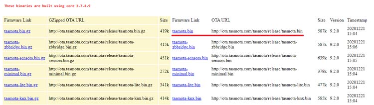
The first step will be downloading the Tasmota firmware file from http://ota.tasmota.com/tasmota/release/. Tasmota has a big list of firmware files with different built-in drivers for various sensors and other devices. If you're a beginner and not sure which file to use, just start with “tasmota.bin”. It includes all the features required for the majority of compatible hardware.
Step2: Preparing Hardware
As mentioned earlier, we will use Arduino Uno as a programmer to flash the firmware on ESP-01. The circuit for connecting ESP-01 with Arduino Uno is given below:

Connections for programming ESP8266 are as follows:
|
ESP8266-01 |
Arduino Uno |
|
VCC |
3.3V |
|
GND |
GND |
|
CH-PD |
3.3V |
|
RX |
RX |
|
TX |
TX |
|
GPIO-0 |
GND |
|
GPIO-2 |
Not Connected |
|
RST |
Initially not connected. Before hitting upload, connect RST to ground and remove after half a second |
Apart from these connections, connect the Reset pin of Arduino to GND to bypass the Arduino. It will disable Arduino and upload code directly to the ESP8266 board. Now, power up the Arduino Uno and open the Arduino IDE. Select the “Generic ESP8266 Module” in Board. Before clicking on Upload, we have to boot ESP-01 into programming mode. For that Ground the RST pin for a second and then click on Upload in your Arduino IDE.
Step 3: Download and install Tasmotizer
Now that we have hardware and firmware ready, it’s time to flash the firmware file on ESP-01. Here, we will use Tasmotizer for flashing the firmware file. It is a specifically designed as flashing tool for Tasmota. You can download the latest Tasmota version from the given link, after that, double click the downloaded file and it'll start without asking for any installation.
Step4: Flashing the Firmware
Finally, choose the port to which the Arduino Uno is connected. Then select the Tasmota firmware file that you downloaded earlier. Tasmotizer also provides you the option of saving the old firmware that is present on your ESP-01. If you want to save your ESP-01 firmware then tick the "Save original firmware" option.
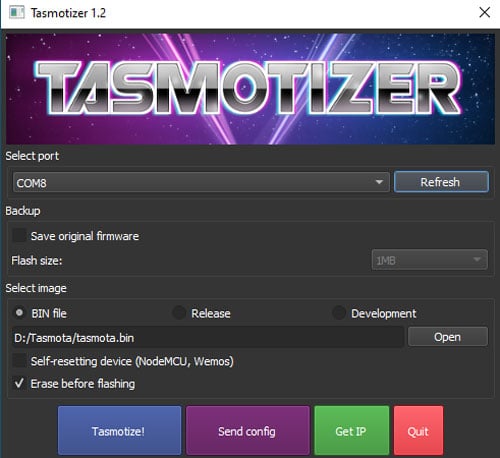
Once you have selected the port and file, click on ‘Tesmotize!’ and wait until it is done.

Step 5: Configure Wi-Fi
Once you are done with flashing the Firmware, disconnect the ESP-01 completely, then reconnect the VCC, GND, and CH_EN pins. When the Tasmota firmware starts up for the first time, it provides a wireless access point for easy Wi-Fi configuration.
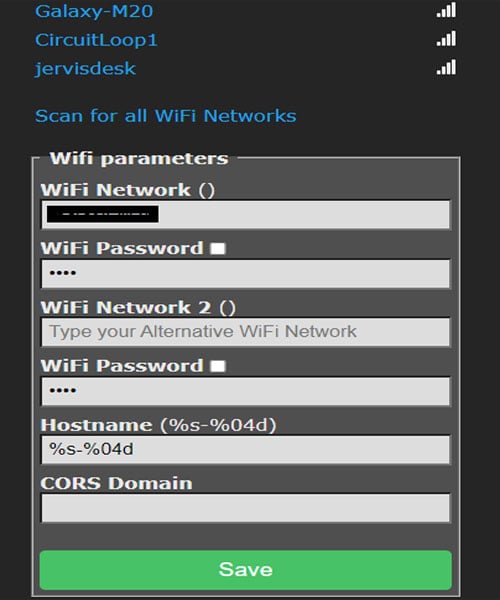
Connect to the Tasmota network that starts with “tasmota_XXXXXX-####” using your Smartphone or laptop, and you will be redirected to the Tasmota configuration page automatically where you can set up the Wi-Fi credentials. Once done click ‘Save’, ESP will restart and connect to the Wi-Fi network that you provided.
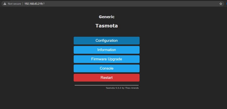
Ok, so now we are done with flashing and configuring Tasmota, it’s time to add and control smart devices using Tasmota Web UI. For that, first find the IP address of your ESP8266 Tasmota device and use that to access the Tasmota UI.
Setting up and Controlling Smart Devices using Tasmota
Tasmota allows you to configure and control any device that uses the ESP Wi-Fi chip. Here, we are using the ESP-01 chip and to control LED and read the DHT11 sensor. With it, we first have to configure Tasmota. For that, first click on the ‘Configuration’ button and then in the next step click on ‘Configure Module.’
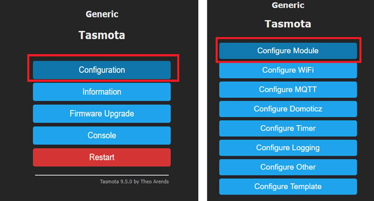
Now, on the ‘Configure Module’ page by default, the module type will be ‘Generic (0)’. Change it to ‘Generic (18)’ i.e. ESP8266 board and save the changes.
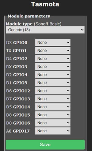
Again, go to the configure module page and select ‘PWM’ to control LED on GPIO2 and DHT11 on GPIO0.
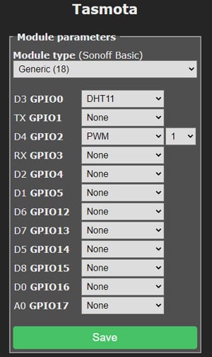
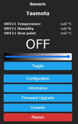
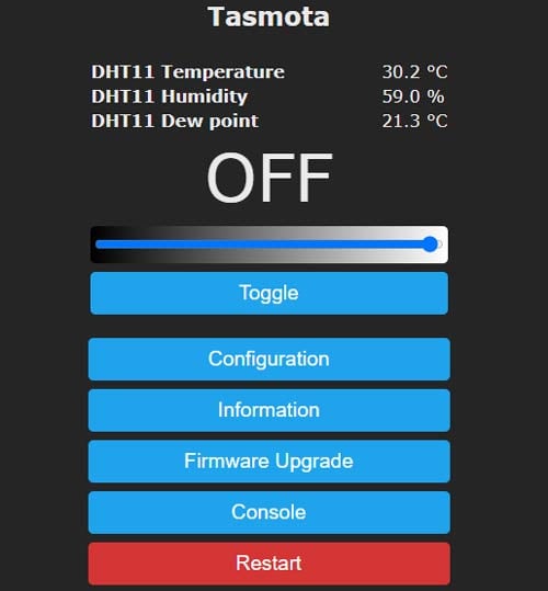
After that, click on ‘Save’ to save the changes. The ESP-01 will restart. Then go to Main Menu and you will have a toggle button with a slider to control the brightness and DHT11 readings on your Tasmota Web UI.
Now, to test whether this works or not, connect an LED to GPIO2 and DHT11 sensor to GPIO 0 of ESP-01 as shown in the below image:
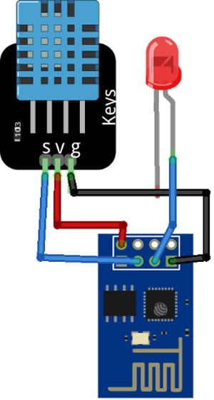
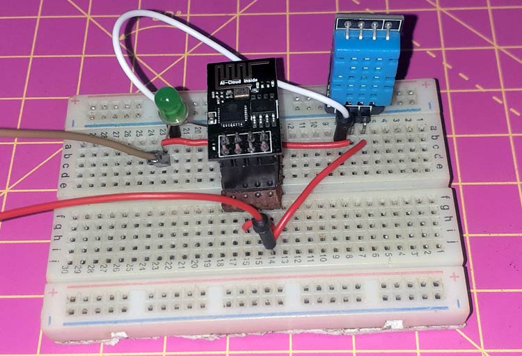
And with this done, DHT11 sensor readings will be displayed on Tasmota Web UI and you can use the toggle switch to turn on/off the LED and slider to change the brightness of the LED.
So, that’s all about how to flash Tasmota on ESP-01 and how to add things and control them. Generally, the process is the same no matter which device you are using. I hope that this tutorial has helped you understand why it is such a good idea to use it on your smart home devices. If you have any questions, please leave them in the comment section below or use our forum to start a discussion on this.
