In India, there are more than 70 lakh wells, that are both Kutcha and Pucca, in the alluvial plain regions. These wells irrigate 38% of the net irrigated area of the country and The traditional homestead type of habitation in Kerala is generally characterized by a well in each compound to tap groundwater. Therefore, it is estimated that the state has around 65 to 70 lakh wells. also, there are many Well Cleaners workers who are dying due to inhaling Toxic Gas while cleaning the well, daily in the newspaper we seeing such news, it is a shame, and we know that India is one of the developing country in means of technology and engineering.
I came up with this project due to an incident that happened in my home state Kerala were four workers died of asphyxiation while cleaning well in Kollam, that incident struck in my heart and I was thinking we had the technology to collect data from spacecraft that were in even outer space, so, why don't we make a solution for the safety of Well Cleaners Workers, I'm an Indian technical enthusiast, so, as an Indian it is my responsibility to make an engineering solution for this problem that Indian well cleaning workers face.
So, I have come up with this, The "Well Cleaners Early Warning System(EWS)" or "Well Cleaners EWS" main goal is to protect workers by giving them early notice of dangerous gas leaks and information they may use to take appropriate action. The device continuously monitors gas levels and can instantly identify any unusual increase in concentrations, alerting to potential concerns. As a result, potential accidents and injuries can be avoided, and workers can take appropriate action to protect themselves and leave the area.
The safety of employees is of utmost concern in homes and workplaces where wells and small spaces are common. These conditions are extremely hazardous to the health of anyone working nearby because of the buildup of toxic gases like hydrogen sulphide (H2S), carbon monoxide (CO), and methane (CH4). The installation of a sophisticated early warning system for toxic gas detection is essential to reducing these risks and ensuring the safety of employees.
The Newspaper Screenshot


The above Newspaper Screenshots show the social irrelevance and Importance of this "Well Cleaners Early Warning System(EWS)" Project. there are many reported and unreported incidents happening in India, also you can find much news regarding this well-cleaners death incident on the internet.
Hence, this "Well Cleaners EWS or Well Cleaners Early Warning System(EWS)" Project has social influence.
Components Required
1)LM2596 × 1
2)OLED Display (Organic Graphic Display Module) × 1
3)LED 3mm × 10
4)Pushbutton Switches (DPDT, H=12.5mm, Soft Push) × 2
5)Toggle Switches (3A 250V, On-Off, SPST, Red LED) × 2
6)HCSR04 × 1
7)L298 driver board(High Current, High Voltage Dual Full Bridge Driver) × 1
8)ESP32 Module × 1
9) ARDUINO R4 WIFI MODULE × 1
10)MT3608 (Step Up Power Module Booster) × 2
11)Buzzer 5V × 1
12)TP5100 (Lithium Battery Charger Protection Module) × 2
13)MQ-4 (Natural Gas Sensor) × 1
14)MQ-7 (Carbon Monoxide Gas Sensor) × 1
15)MQ-136 (Sulfur Dioxide Gas Sensor) × 1
16)100RPM Gear motor × 1
17)Battery Voltage Monitor (with TL431 Adjustable Precision Zener Shunt Regulator) × 2
18)TL431 (Adjustable Precision Zener Shunt Regulator) × 2
19)Resistors and Capacitors (Various types) × 4
Power Supplies:
20)Lithium Ion Cell 3.7V × 3
Accessories and Tools:
21)Wire (Hook-up Wire, Red, 100 FT) × 2
22)Hot Glue Gun × 1
23)Solder Sucker × 1
24)Soldering Iron Gun × 1
25)Female DC Power Jack Adapter Connector Plug (for Motor connection) × 1
26)DOT Board (Prototyping material) × 2
Mechanical Components:
27)Nut and Bolt (3mm*40mm) × 9
28)Nut and Bolt (3mm*150mm) × 1
29)6mm Flange Coupling (Fixed Rigid Flange Plate Shaft Connector) × 1
30)PVC Pipes 1M × 1
31)4mm Forex Sheet (500mm*500mm, for enclosure making) × 1
32)Screw Driver (for 3mm screws) × 1
Other:
33)Polymer Thread (Rope type) × 1
34)Spray Paint (Black) × 1
Building
Main Components section:
Arduino UNO R4 WiFi: A microcontroller board with built-in Wi-Fi, part of the Arduino UNO family, it combines the ease of use of the classic UNO with the power of modern connectivity. Ideal for IoT applications, it is compatible with Arduino IDE and features the same form factor as the original UNO for ease of integration into existing projects.
ESP-32: ESP32 is a series of low-cost, low-power system on a chip microcontrollers with integrated
Wi-Fi and dual-mode Bluetooth. The ESP32 series employs either a Tensilica Xtensa
LX6 microprocessor in both dual-core and single-core variations, Xtensa LX7 dual-core
microprocessor or a single-core RISC-V microprocessor and includes built-in antenna switches,
RF balun, power amplifier, low-noise receive amplifier, filters, and power-management
modules. ESP32 is created and developed by Espressif Systems, a Shanghai-based Chinese
company, and is manufactured by TSMC using their 40 nm process. It is a successor to the
ESP8266 microcontroller.LM2596: This DC-DC Step-Down Buck Converter Power Supply Module provide all the active
functions for a step-down (buck) switching regulator, capable of driving a load up to 5A with
excellent line and load regulation. This module comes with variable but the fixed value of
input i.e. 24V, 12V, and 9V as well as fixed output voltage which is 5V 5A. The module
requires a minimum number of external components, these regulators are simple to use and
include internal frequency compensation, and a fixed frequency oscillator. Hence it
replaces the purpose of LM2596S.OLED Display: OLED (Organic Light-Emitting Diodes) is a flat light-emitting technology, made by
placing a series of organic thin films between two conductors. When an electrical current is applied, a bright light is emitted. OLEDs are emissive displays that do not require a backlight and so are thinner and more efficient than LCDs (which do require a white backlight).MT3608: The MT3608 2A Max DC-DC Step Up Power Module Booster Power Module is a
low-cost module that can step up a 2 to 24V input voltage up to a 5 to 28V output at up to
2A. DC-DC boost converters step up the input voltage to a higher voltage while also stepping
down the available current since the module can’t output more power than its inputs. This
boost converter is adjustable and capable of outputting a voltage in the range of 5.0 to 28V
at a continuous current of up to 1.5A depending on input/output voltage settings with 1A
available with most settings. Since it is a boost converter, the input voltage must be lower
than the output voltage. The device can use low ESR bulk ceramic capacitors rather
than electrolytic caps which avoids long-term aging concerns and contributes to the compact
packaging. The MT3608 converter IC has over-current and thermal limiting features built in
to safely shut the device down if driven too hard.Lithium-ion cell(3.7V): A lithium-ion cell with a voltage rating of 3.7V is a rechargeable battery commonly used
in various electronic devices, including smartphones, tablets, laptops, and portable electronic gadgets. It is a type of rechargeable battery that utilizes lithium ions as the primary charge carriers. The cell consists of several components, including an anode, a cathode, and an electrolyte solution.TP5100 BMS: The TP5100 is a compact and versatile charging IC specifically designed for single-cell
lithium-ion and lithium-polymer batteries. It integrates multiple functions required for battery charging, such as constant current control, constant voltage control, and overcharge protection. The IC typically comes in a small form factor and is commonly used in applications like power banks, handheld devices, and other battery-powered electronics.Battery voltage monitor Circuit: A battery voltage circuit is a circuit designed to measure and monitor the voltage of a battery. It is commonly used in various electronic devices, automotive systems, and power
management applications to ensure the proper functioning and health of the battery.MQ-4: As a natural gas sensor, the MQ-4 Natural Gas Sensor is a fast and reliable sensor with a high sensitivity to natural gas and Methane, also good sensitivity to propane and butane. This natural gas sensor has a long life and low cost and is widely used for gas leak detection.
MQ-7: Sensitive material of the MQ-7 gas sensor is SnO2, which with lower conductivity in clean air. It makes detection by method of cycle high and low temperature and detects CO when low temperature (heated by 1.5V). The sensor’s conductivity is higher along with the gas concentration rising. When the high temperature (heated by 5.0V), it cleans the other gases adsorbed under low temperatures. Please use a simple electrocircuit and convert the change of conductivity to the corresponding output signal of gas concentration. MQ-7 gas sensor has a high sensitivity to Carbon Monoxide. The sensor could be used to detect different gases containing CO, it is at low cost and suitable for different applications.
MQ-136: MQ136 is a gas sensor module designed to detect the presence of hydrogen sulfide (H2S) gas in the surrounding environment. It utilizes a tin dioxide (SnO2) semiconductor as its sensing element. The MQ136 sensor module is commonly used in various applications such as industrial safety, environmental monitoring, and gas leakage detection.
HCSR04: The HCSR04 is an ultrasonic distance sensor commonly used in robotics and automation projects. It utilizes ultrasonic waves to measure distances between objects and provides accurate distance measurements within a specified range.
100RPM Gear motor: A 100rpm motor refers to a motor that rotates at a speed of 100 revolutions per minute.
The term ”100rpm motor” is a general description of the motor’s rotational speed and does not provide specific details about the motor’s type or construction. Speed: The motor operates at a constant speed of 100 revolutions per minute.L298 driver board: The L298 driver board is based on the L298N dual H-bridge motor driver IC. It consists
of an L298N IC mounted on a PCB along with the necessary circuitry for motor control. The board offers a convenient interface and power stage for connecting and controlling motors, making it a popular choice for hobbyists and professionals alike. Dual H-Bridge Configuration: The L298 driver board features a dual H-bridge configuration, which allows independent control of two DC motors or one bipolar stepper motor. Each
H-bridge can handle currents up to 2A per channel (with a maximum peak of 3A). Motor Direction and Speed Control: The board provides easy control over motor direction and speed. By applying appropriate logic signals to the control pins, you can change the motor direction (forward or reverse) and adjust the speed using pulse-width modulation (PWM) signals.TL431: TL431 is an Adjustable Precision Zener Shunt Regulator.
Buzzer 5V: This voltage buzzer is generally used in alarm circuits, communication equipment, piezo, and Automobile electronics. This is small, durable, and easy to use. This product normally operates on 5v DC and its current rating is less than equal to 30maA.
SOFTWARE REQUIREMENT
Arduino IDE: The Arduino IDE (Integrated Development Environment) is a multipurpose application that can be used for multiple operating software like Windows, macOS, Linux, and operating systems that are programmed in C and C++. It is helpful to code the required commands and can be written to any compatible board. Software download link
Tinkercad: Tinkercad is a free, web-based application that provides tools for 3D design, electronics simulation, and coding. It's particularly popular in education for teaching STEM (Science, Technology, Engineering, and Mathematics) concepts. link.
CH340 DRIVER: The CH340 is a USB-to-serial (UART) interface chip often used in microcontrollers and other embedded systems. If you need drivers for the CH340, you can download them from the official website or other trusted sources. Here are the steps for downloading and installing the CH340 driver on different operating systems, Want to install the CH340 Driver to the computer to detect the ESP32 board Driver download link
EasyEDA: EasyEDA is a web-based EDA tool suite that enables hardware engineers to design, simulate, share - publicly and privately - and discuss schematics, simulations, and printed circuit boards. link.
N.B: While doing this Project you are to refer to the Schematics, and Project Codes(Which are attached), in the Schematic due to unavailable of the various modules used in this project(I have designed the various modules and wired) in the market the modules used in this project is available, so the connection is easy, you can edit the pinouts in the project code according to your ESP and Arduino UNO R4 WiFi Pinout Selection, Just go through the Testing Video(attached ), Circuit Schematics, Project TX AND RX Code(attached in this Project) and Read the full Details of the Project in the Building Section and Block Diagram(from Block Diagram itself you can understand the Connections of the various Modules Used in this Project) and All the Resistor & Capacitor Values are there in the Schematic(Attached in this Project), (Using of connectors are Optional).
BLOCK DIAGRAM :
1.Transmitter(TX) Or Sensor Module
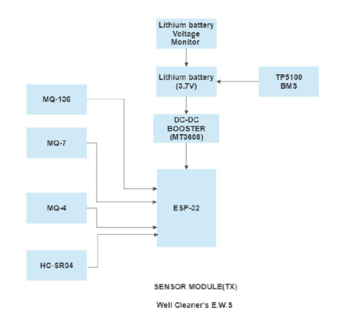
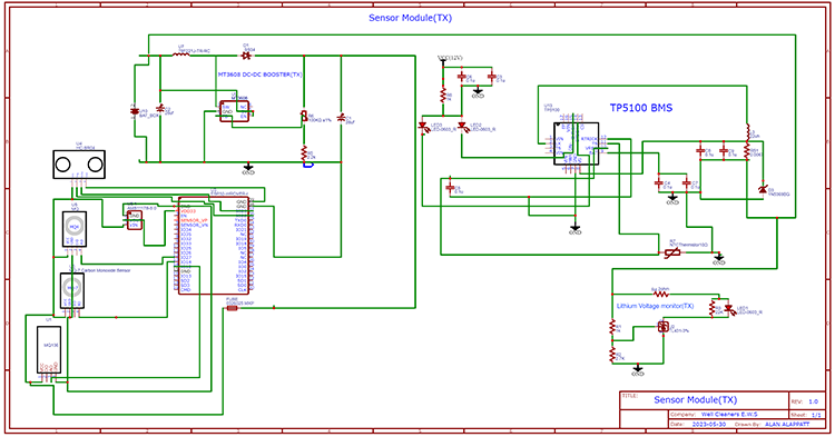
The block diagram consists of a lithium battery(3.7) which is monitored by a lithium battery voltage monitor and TP5100 BMS, DC-DC booster(MT3608) to step up the voltage from 3.7v to 5v to ESP-32. The sensors MQ-136 (detection of hydrogen sulfide), MQ-7(detection of carbon monoxide), MQ-4(detection of methane gas), and HC-SR04(ultrasonic sensor to detect distance from water level) are connected to the ESP-32.
Here the sensor module acts as a Transmitter.
2. Receiver(RX) or Control Module:
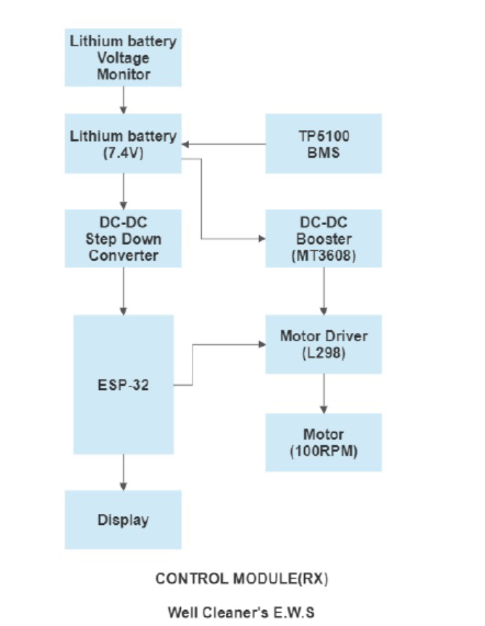
N.B: ESP32 IN THE CONTROL MODULE(RX) BLOCK DIAGRAM IS REFERS TO THE ARDUINO UNO R4 WiFi MODULE.
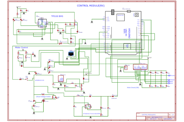
The block diagram consists of two lithium batteries (7.4v) which are connected in series (3.7v each), a Lithium battery voltage monitor monitors them, and TP5100 BMS, LM2596 DC-DC step-down converter is used to provide constant voltage (5v) to Arduino UNO R4 WiFi module and the display is used to show the readings or data transmitted from sensor module through Arduino UNO R4 WiFi module, DC-DC booster (MT3608) is to step up the voltage from 7.4v to 12v and also to provide power to the motor driver(L298) and motor(100RPM). Here the control module operates as a Receiver.
The system is developed using ESP32, this project uses two ESP32s, one ESP32 is a Transmitter(TX) and the other ESP32(Arduino UNO R4 WiFi) will be a Receiver(RX), these ESP32s will communicate by using a communication protocol called ESP NOW.
ESP-NOW is a connectionless communication protocol developed by Espressif that features short packet transmission. This protocol enables multiple devices to talk to each other without using Wi-Fi. This is a fast communication protocol that can be used to exchange small messages (up to 250 bytes) between ESP32 boards. ESP-NOW is very versatile; you can communicate in different arrangements in one-way or two-way communication.
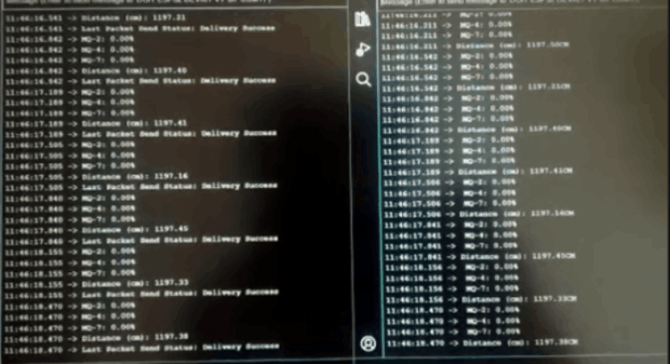
The above picture is a serial monitor data of the project output to ensure it is exchanging data (various gas sensor readings and ultrasonic sensor readings) between two esp32
(one ESP32 is on Arduino UNO R4 WiFi module)
I have used various gas sensors such as MQ-4(methane (CH4)), MQ-7(carbon monoxide (CO)), and MQ-136(hydrogen sulfide (H2S)), these sensors can detect the toxic gases that I mentioned before, these gas sensors are connected with the transmitter(TX) side and the reading will display in the OLED display which is in the Receiving (RX) side, the data are transmitted by the communication protocol.
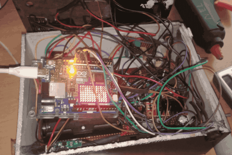
Receiver(RX) or Control Module assembling below figure:
Transmitter(TX) or Sensor Module side assembling below figure
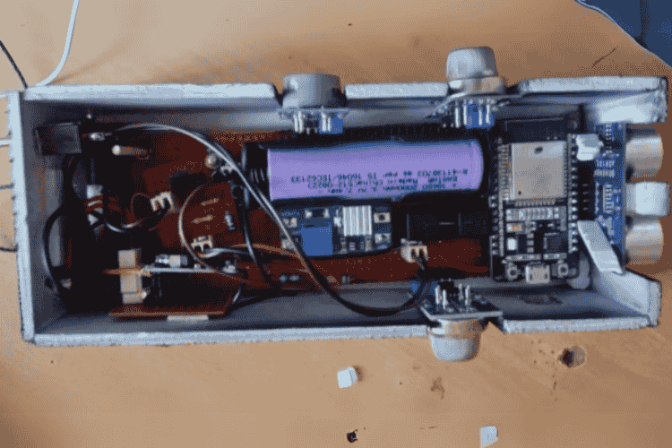
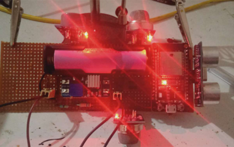
Transmitter(TX) or Sensor Module: As I mentioned earlier, it uses gas sensors, an ultrasonic sensor, a lithium-ion battery, a BMS module, a step-up converter, and a battery voltage monitor circuit.
This transmitter (TX) Module goes down to the well to detect any toxic gas presence and give an alert to the workers before they enter the well for cleaning, the receiver(RX) Also Called the Control panel is used to control the entire device,
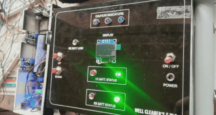
Receiver(RX) or Control Module: consists of 2 lithium-ion batteries, a BMS Module, a step-up and step-down converter, battery voltage monitor, caution indicators, safety buzzer, battery charging status indicators, motor control buttons, display..etc.
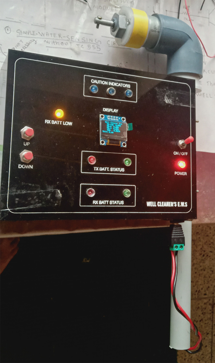
Receiver (RX) s panel assembling figure :
The transmitter(TX) goes down to the well is using a pully system with a gear motor, which uses a 100RPM motor to deliver the torque, with the combination of the motor driver called L298, an HCSR04 or ultrasonic sensor used as a safety feature of this device, if the operator of this device continuously press the DOWN button in the receiver(RX) or Control Module, the transmitter(TX) module goes down and high chance of a dip in the water in the well, which damage the transmitter(TX) module circuits due to water enters in the PCB and sensors, so, as a safety feature in order to protect the TX module from this, used a ultrasonic sensor, the motor in the pully system(receiver(RX) side)will stop if the transmitter(TX) module is 25CM above the water in the well.
The below figure is a battery voltage monitor circuit
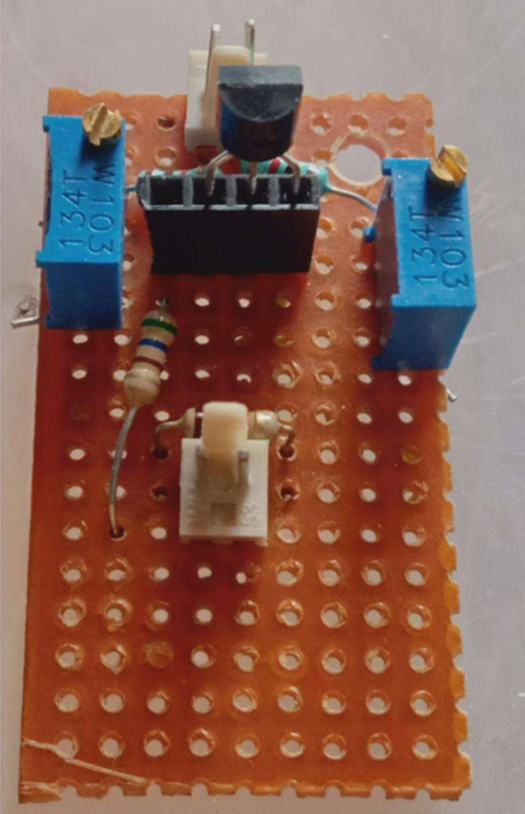
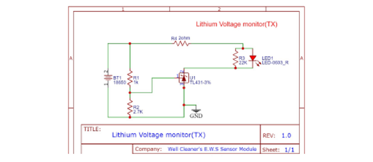
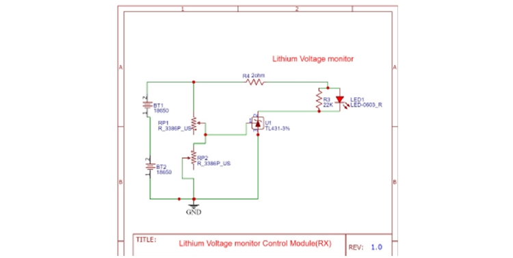
Battery voltage monitor circuit that is also included in order to monitor the battery in the transmitter(TX) module and Receiver (RX) module, in battery voltage monitor circuit uses a TL431 (pictured below) is an Adjustable Precision Zener Shunt Regulator. Its output voltage can be set to any value between 2.5V and 36V with the use of two external resistors (acting as a voltage divider). ith very sharp turn-on characteristics, the TL431 is an excellent alternative to a zener diode in many applications. In this article we will look at how a TL431 can be used to make a very simple battery status monitor illuminating an LED("RX BATT LOW" in the control panel) when the input voltage is above a user-set value.
1. Battery voltage monitor circuit of Transmitter(TX) or Sensor Module Schematic:
2. Battery voltage monitor circuit of Receiver (RX) or Control Module Schematic:
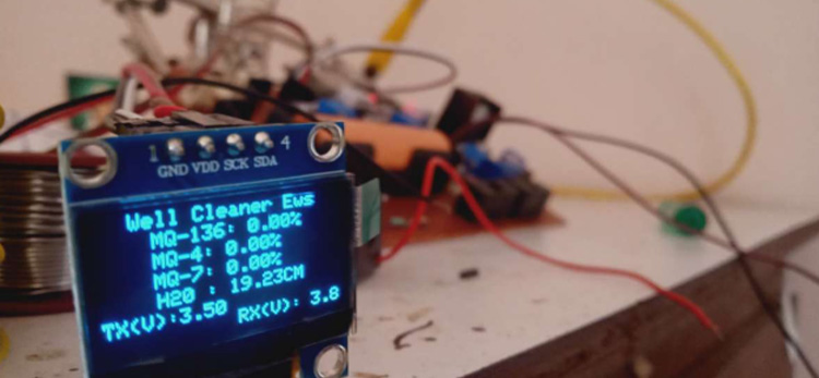
The Below figure is taken during the testing of the circuit, the old display shows the gas presence in percentage and H20 mentioned in the display is ultrasonic sensor readings:
Transmitter(TX) or Sensor Module Circuit Assembling
Transmitter(TX) or Sensor Module making with Forex Sheet:
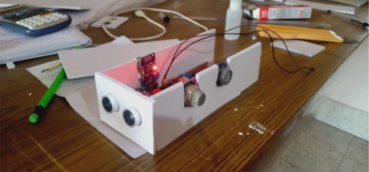
To reduce the cost of the device I have avoided 3D printing, so, I have used a 4mm Forex sheet to make the transmitter(TX) module and Receiver (RX) Module Enclosure, the dimensions we can edit according to your idea.
We can Cut the 4mm Forex sheet with a blade or cutter, after that we can spray paint the Forex Sheet Enclosure for more finishing(i have used black spray paint).
The Below 2 PCBs are transmitter(TX) and Receiver (RX) modules Dot PCB Prototype:
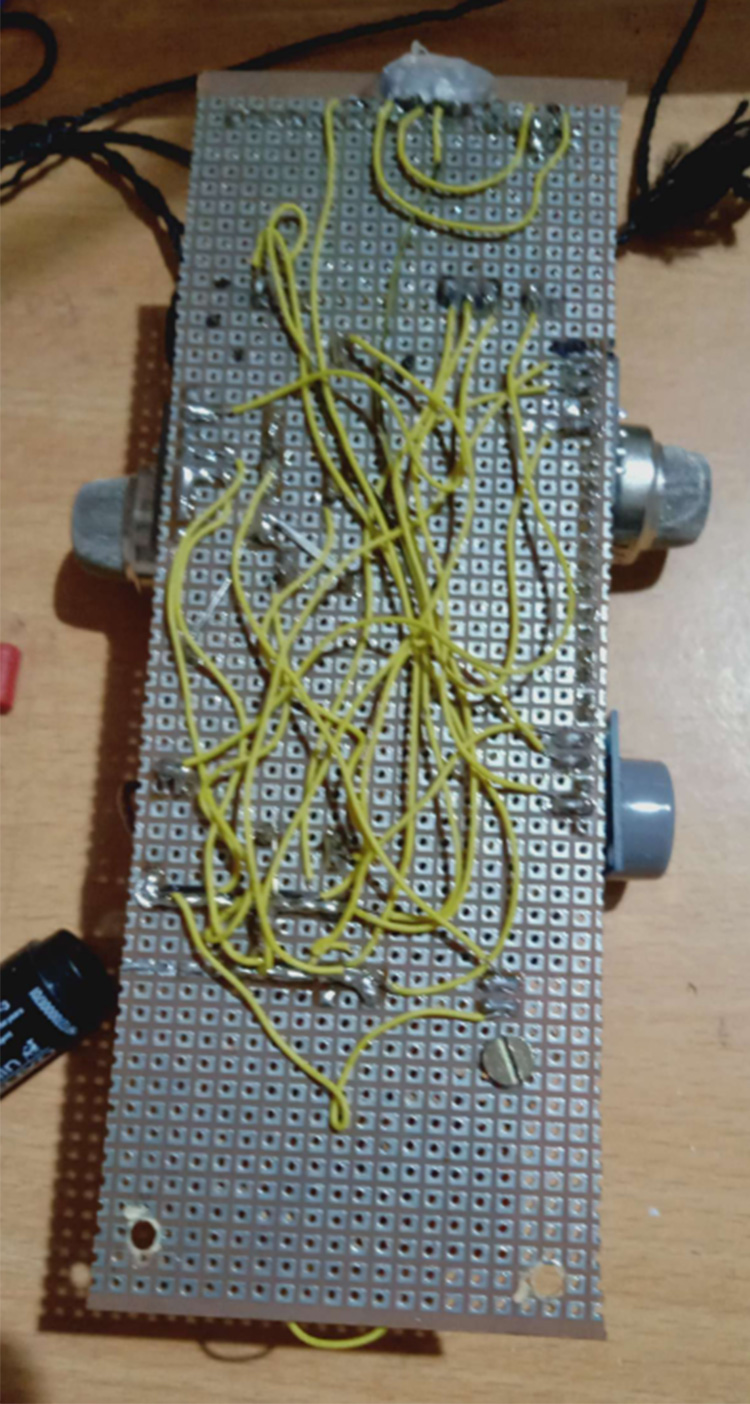
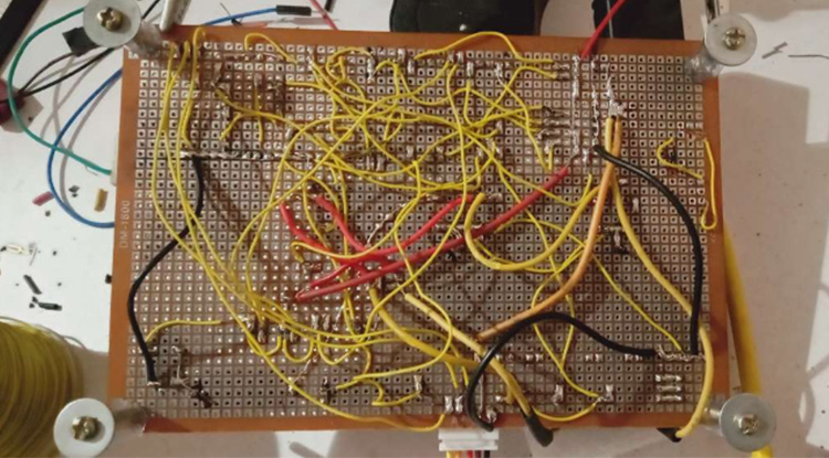
The above 2 PCBs are transmitter(TX) and Receiver (RX) modules, this is a prototype, that's why I have just done it on the dot PCB board.
In this project, we have used Lithium-ion batteries in order the Power these 2 Modules( Receiver(RX) & transmitter(TX)),
Sensor module or Transmitting(TX): In this Module consists of one Lithium-ion(3.7V)(4.2V @ full charge) (With 3.7V 18650 Battery Holder), and
Control module or Receiver(RX): In this Module consists of 2 Lithium-ion(3.7V+3.7V=7.4V)(4.2V+4.2V=8.4V @ full charge) (With 3.7V 18650 Battery Holder) cells connected in series, because of the pully system, the gear motor in the Pully system in the control module(RX) which need more voltage and this is connected it step-up module to boost 8.4V to 12V(motor and motor driver operate in 12V), the battery is connected with TP5100 BMS module.
sensor module or transmitting(TX): in this Module, used step-up converter (MT3608)which will boost 3.7V to 5V(ESP32, MQ series and ultrasonic sensors and battery voltage monitor operates in 5V) .
Control module or Receiver(RX): in this module used an Arduino UNO R4 WiFi module, a step-up converter(MT3608) and step-down converter(LM2596), The step-up converter input is connected to the 2 series lithium-ion battery hence the output of this is connected to the Motor Driver, and Gear motor(100RPM) of pully system.
The step-down converter(LM2596) input is connected with the 2 series lithium-ion battery(8.4V) hence the output(5V) of this is connected to ESP32, OLED display, buzzer, and indicators For Powering.
The Transmitting(TX) & Receiver(RX) Modules can charge With a 5V,500mA Adaptor.
N:B: Refer to the Circuit Diagram for the Circuit Connection.
Pully system with Motor Picture
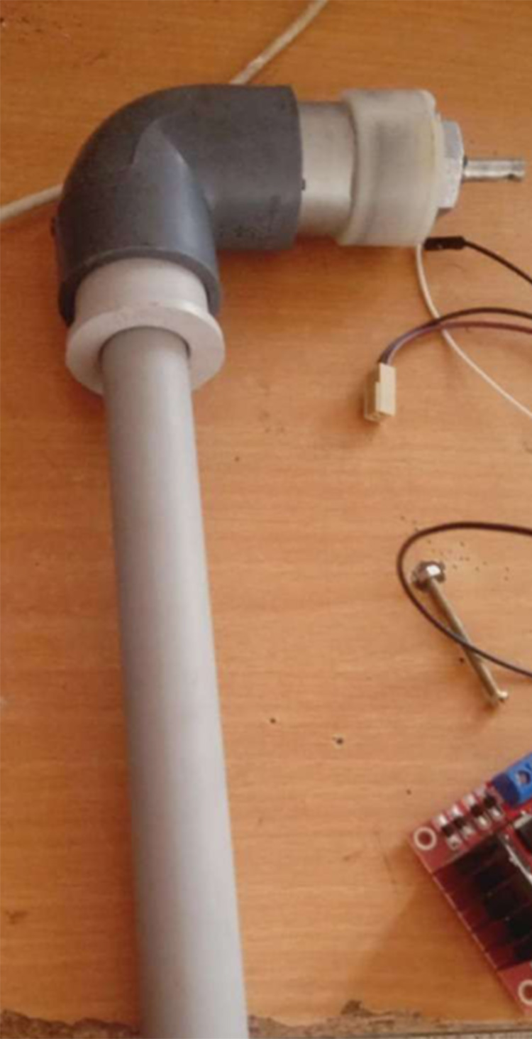
The above Picture is the Pully System Which is Made With PVC Pipe and a PVC Bracket, the PVC Bracket is Used to Attach the 100RPM Motor, after fitting the PVC Bracket with the Motor And joining it with 30CM PVC Pipe as shown in the Picture, after that it is attached to the Receiver Enclosure with two 3MM Nut & Bolt(want to drill a 3MM hole in Forex Sheet enclosure and PVC Pipe).
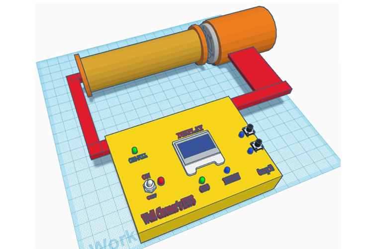
Cad Model of Control Module Panel
For More Professional, we can able to design using CAD software/Drawing according to your idea and done in acrylic sheet using laser cutting, and can be locally made.
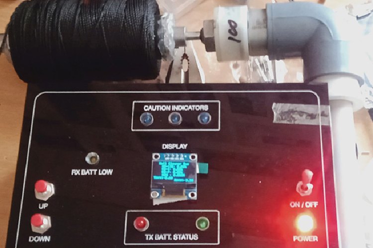
The above picture is the complete work done as a prototype of the Control module or Receiver(RX)
The transmitter(TX) module goes down to the well, with the help of the motor and a polymer thread(black color), polymer thread is strong enough to hold the transmitter(TX) module.
The Prototype Can Tested with a Gas Electric Lighter the LPG gas can vary the Gas Sensors in the Transmitter(TX) module, The MQ Series Gas Sensor has Cross Sensitivity(for example if MQ-4 is a Methene sensor that can detect methane and LPG gas, suppose methene present 50% in the MQ-4 Sensor Premises the Sensor shows 50% in Display, but if the LPG Gas present 50% in the MQ-4 Sensor Premises the Sensor shows 10% Approx in Display.)
The Below Video (LINK) is the Testing of the Transmitter(TX) and Receiver (RX) with a Gas Electric Lighter (LPG Gas)(the Sensor Reading in the Serial monitor and OLED Display on the Receiver (RX) or Control Module)
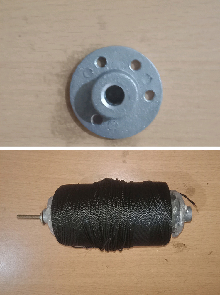
The Below Figure is a Flange Plate Shaft Connector & polymer thread (black color)
Used 6mm Flange Coupling Fixed Rigid Flange Plate Shaft Connector.
polymer thread can be purchased in local Shops.
The flange Plate Shaft Connector is connected to the 100RPM Gear Motor and the other end of the Shaft Connector is screwed with a 3mm 15 CM Nut and bolt.
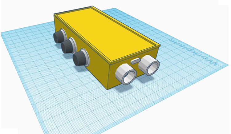
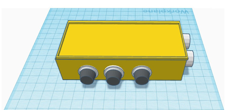
3D Pictures of the Well Cleaners Early Warning System(EWS):
Control Module or RX 3D view
Sensor Module or TX 3D view:
The Below picture is the complete work done on a prototype of the Control module or Receiver(RX) and sensor module or transmitting(TX):
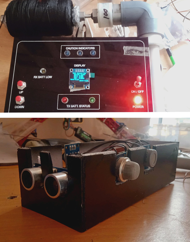
The "Well Cleaners Early Warning System(EWS)" or "Well Cleaners EWS" main goal is to protect workers by giving them early notice of dangerous gas leaks and information they may use to take appropriate action. The device continuously monitors gas levels and can instantly identify any unusual increase in concentrations, alerting to potential concerns, if the toxic gas is present in the well the buzzer and caution indicator(One the Control Panel) go ON and also display the various gas concentrations on the OLED display in Percentage, hence this Well Cleaners EWS device can save lots lives of the Well cleaning workers.
The "Well Cleaners EWS" Prototype Trial run result is Good and this Prototype was Tested in the Well, hence it proves the Technology Used in this Project Is Very Efficient and Accurate, The Testing Video is also attached.
This Well Cleaners EWS or Well Cleaners Early Warning System(EWS) the Total Project Cost is ₹5700 ($67.75 USD).
The Technology used in this Well Cleaners EWS Project Is Very Efficient and also it is Cost-effective Project, there are many ways to implement this project using CAT6 with RS485 or Lora Module for Transmitting sensor data Between the Transmitter(TX) module and Receiver (RX) Module, all these are Costly Method, that's why I have used ESP32 NOW Protocol to Transmit sensors data Between the Transmitter(TX) module and Receiver (RX) Module, hence Well Cleaners EWS Project Efficient and Cost-effective Project.This project can develop into an entrepreneurship program and also there is a high possibility of productization.
This Well Cleaners EWS Project 80% is in Product Form, Remaining 20% can be finished if I get R&D and Manufacturing Financial Support, I can get this project to come into the market which can Save many Well-Cleaning workers,
hence this project also has Social influence and solves the Social Problem.
Sensor Module Schematic
Control Module Schematic
Thanks For Circuitdigest and DigiKey For Providing me the Hardware Support.
Complete Project Code
// Well Cleaners Early Warning System’s" or "Well Cleaners EWS
// PROJECT MADE BY ALAN ALAPPATT
//EWS  Receiver(RX) or Control Module CODE
#include <WiFi.h>                                   //Well Cleaners EWS RX CODE
#include <esp_now.h>
#include <Adafruit_GFX.h>
#include <Adafruit_SSD1306.h>
#include <Wire.h>
#define SCREEN_WIDTH 128
#define SCREEN_HEIGHT 64

#define BUTTON_PIN1 34
// ESP32 pin GIOP34, which connected to button
#define BUTTON_PIN2 39
// ESP32 pin GIOP39, which connected to button
#define LED_PIN1    25  // ESP32 pin GIOP18, which connected to led
#define LED_PIN2    4
// variables will change:
int button_state1 = 0;
int button_state2 = 0;  // variable for reading the button status

int analoginput = 36; // adc input
float R1 = 56000.0; // resistance of R1 (56K)
float R2 = 100000.0; // resistance of R2 (100K)
int enable1Pin = 14;
// Setting PWM properties
const int freq = 30000;
const int pwmChannel = 0;
const int resolution = 8;
int dutyCycle = 200;

// Create an OLED display object
Adafruit_SSD1306 display(SCREEN_WIDTH, SCREEN_HEIGHT, &Wire, -1);
// Define data structure
typedef struct struct_message {
 float mq136Con;
 float mq4Con;
 float mq7Con;
 float analogInput1;
float distanceCm;

 int ident1;
} struct_message;

// Create structured data object
struct_message myData;
// Callback function that will be called when data is received
void OnDataRecv(const uint8_t * mac, const uint8_t *incomingData, int len) {
 // Get incoming data
 memcpy(&myData, incomingData, sizeof(myData));

}
void setup() {
pinMode(2, OUTPUT);
pinMode(19, OUTPUT);
pinMode(18, OUTPUT);
pinMode(33, OUTPUT);
pinMode(enable1Pin, OUTPUT);
ledcSetup(pwmChannel, freq, resolution);
ledcAttachPin(enable1Pin, pwmChannel);
// initialize the LED pin as an output:
 pinMode(LED_PIN1, OUTPUT);
 pinMode(LED_PIN2, OUTPUT);
 // initialize the button pin as an pull-up input:
 // the pull-up input pin will be HIGH when the button is open and LOW when the button is pressed.
 pinMode(BUTTON_PIN1, INPUT_PULLUP);
 pinMode(BUTTON_PIN2, INPUT_PULLUP);
 // Set up Serial Monitor
 Serial.begin(115200);

 // Initialize OLED display
 if(!display.begin(SSD1306_SWITCHCAPVCC, 0x3C)) {
   Serial.println(F("SSD1306 allocation failed"));
   for(;;); // Don't proceed, loop forever
 }
 display.clearDisplay();

 // Start ESP32 in Station mode
 WiFi.mode(WIFI_STA);

 // Initalize ESP-NOW
 if (esp_now_init() != 0) {
   Serial.println("Error initializing ESP-NOW");
   return;
 }

 // Register callback function
 esp_now_register_recv_cb(OnDataRecv);
}
void loop() {

 float analogvalue = 0;
float vout = 0;
float vin = 0;
 // Reading potentiometer value
 for (int k = 0; k < 100; k++) {
   analogvalue += analogRead(analoginput);


 }
 analogvalue /= 100; // calculate the average value
vout =  (analogvalue * 3.3) / 4095.0; // convert analog value to voltage
 vin = vout / (R2/(R1+R2));

 // Checking for undesired readings
 if (vin < 0.09) {
   vin = 0; // set voltage to 0 if it's less than 0.09V
 }


 // Print received data to Serial Monitor
 Serial.print(" MQ-136: ");
 Serial.print(myData.mq136Con);
  Serial.println("%");
 Serial.print(" MQ-4: ");
 Serial.print( myData.mq4Con);
  Serial.println("%");
 Serial.print(" MQ-7: ");
 Serial.print(myData.mq7Con);
 Serial.println("%");
 // Prints the distance in the Serial Monitor
 Serial.print("Distance (cm): ");
 Serial.print(myData.distanceCm);
  Serial.println("CM");


 if (myData.mq136Con < 20) {  // percentage
   digitalWrite(2, LOW);
 } else {
   digitalWrite(2, HIGH); // Turn off LED

 }
 if (myData.mq4Con < 20) {  // percentage
   digitalWrite(19, LOW);  //on led
 } else {
   digitalWrite(19, HIGH); // Turn off LED

 }
  if (myData.mq7Con < 20) {  // percentage
   digitalWrite(18, LOW);
 } else {
   digitalWrite(18, HIGH); // Turn off LED

 }


// Read the state of the button value:
button_state1 = digitalRead(BUTTON_PIN1);
button_state2 = digitalRead(BUTTON_PIN2);
// Check distance sensor reading
if (myData.distanceCm >= 4 && myData.distanceCm <= 60 && button_state1 == HIGH)
{  // If distance is less than 35 cm
 ledcWrite(pwmChannel, 0);
 digitalWrite(LED_PIN1, LOW);
 digitalWrite(LED_PIN2, LOW);
}
// Control LED and motor according to the state of the button
else if (button_state2 == LOW && button_state1 == HIGH)
{
 // If button 2 is pressed
 // Set motor speed to maximum
 ledcWrite(pwmChannel, 100);
 digitalWrite(LED_PIN1, LOW);
 digitalWrite(LED_PIN2, HIGH);
 // Code to run motor in reverse here (module down)
 // ...
}
else if (button_state1 == LOW && button_state2 == HIGH)
{
 // If button 1 is pressed
 // Set motor speed to maximum
 ledcWrite(pwmChannel, 140);
 digitalWrite(LED_PIN1, HIGH);
 digitalWrite(LED_PIN2, LOW);
 // Code to run motor forward here (module up)
 // ...
}
else
{
 ledcWrite(pwmChannel, 0);
 digitalWrite(LED_PIN1, LOW);
 digitalWrite(LED_PIN2, LOW);
 // Stop motor
 // ...
}


display.clearDisplay();
display.setTextColor(WHITE);
 display.setTextSize(1);      // Display well cleaner ews
 display.setCursor(15, 0);
 display.print("Well Cleaner Ews");
display.setTextSize(1);
 display.setTextColor(WHITE);
 display.setCursor(25,10);
 display.print("MQ-136: ");
 display.print(myData.mq136Con);
  display.print("%");
display.setTextSize(1);
 display.setCursor(25,20);
 display.print("MQ-4: ");
 display.setTextColor(WHITE);
 display.print(myData.mq4Con);
  display.print("%");
display.setTextSize(1);
 display.setTextColor(WHITE);
 display.setCursor(25,30);
 display.print("MQ-7: ");
 display.print(myData.mq7Con);
  display.print("%");   //Serial.println(temperature);
  display.setTextSize(1);
 display.setTextColor(WHITE);
 display.setCursor(20,40);
 display.print(" H20 : " );
 display.print(myData.distanceCm);
 display.print("CM");

 display.setTextSize(1);
 display.setTextColor(WHITE);
 display.setCursor(0,50);
 display.print("TX(V):");
 display.print(myData.analogInput1);
 display.display();

delay(550);
}
// Well Cleaners Early Warning System’s" or "Well Cleaners EWS
// PROJECT MADE BY ALAN ALAPPATT
// Well Cleaners EWS Transmitter(TX) or Sensor Module CODE:
// Include required libraries  // TX
#include <WiFi.h>
#include <esp_now.h>                                   // Well Cleaners EWS TX CODE
int analoginput = 36;
//float R1 = 56000.0; // resistance of R1 (56K)
//float R2 = 100000.0; // resistance of R2 (100K)

// Define MQ Sensor pins
#define MQ136 34
#define MQ4 32
#define MQ7 35
const int trigPin = 23;
const int echoPin = 22;
//define sound speed in cm/uS
#define SOUND_SPEED 0.034
#define CM_TO_INCH 0.393701

// Sensitivity curves for MQ-136, MQ-4, and MQ-7 sensors
const float MQ136_SENSITIVITY = 0.4;   // ppm per % hydrogen
const float MQ4_SENSITIVITY = 0.4;   // ppm per % methane
const float MQ7_SENSITIVITY = 0.35;  // ppm per % carbon monoxide
//Calib values
float mq136SensorCalib = 0;
float mq4SensorCalib = 0;
float mq7SensorCalib = 0;
//Offset values
float mq136Offset = 0.5;
float mq4Offset = 0.5;
float mq7Offset = 0.5;
// Integer for identification (make unique for each transmitter)
int ident = 2;
// Responder MAC Address (Replace with your responders MAC Address)
uint8_t broadcastAddress[] = { 0x3C, 0xE9, 0x0E, 0x89, 0xB8, 0xD8 };
// Define data structure
typedef struct struct_message {
 float mq136Con;
 float mq4Con;
 float mq7Con;
 float analogInput1;
float distanceCm;

 int ident1;
} struct_message;
// Create structured data object
struct_message myData;
// Register peer
esp_now_peer_info_t peerInfo;
// Sent data callback function
void OnDataSent(const uint8_t *macAddr, esp_now_send_status_t status) {
 Serial.print("Last Packet Send Status: ");
 Serial.println(status == ESP_NOW_SEND_SUCCESS ? "Delivery Success" : "Delivery Fail");
}
void setup() {

 // Setup Serial monitor
 Serial.begin(115200);

 pinMode(trigPin, OUTPUT); // Sets the trigPin as an Output
 pinMode(echoPin, INPUT); // Sets the echoPin as an Input
 // Set ESP32 WiFi mode to Station temporarly
 WiFi.mode(WIFI_STA);
 // Initialize ESP-NOW
 if (esp_now_init() != 0) {
   Serial.println("Error initializing ESP-NOW");
   return;
 }
 // Define callback
 esp_now_register_send_cb(OnDataSent);
 memcpy(peerInfo.peer_addr, broadcastAddress, 6);
 peerInfo.channel = 0;
 peerInfo.encrypt = false;
 if (esp_now_add_peer(&peerInfo) != ESP_OK) {
   Serial.println("Failed to add peer");
   return;
 }
 // Perform calibration
 float mq136Val = 0;
 float mq4Val = 0;
 float mq7Val = 0;
 for (int i = 0; i < 100; i++) {
   mq136Val += analogRead(MQ136);
   mq4Val += analogRead(MQ4);
   mq7Val += analogRead(MQ7);
   delay(25);
 }
 mq136Val = mq136Val / 100;
 mq4Val = mq4Val / 100;
 mq7Val = mq7Val / 100;
 mq136SensorCalib = (mq136Val / 4095.0) * 100;
 mq4SensorCalib = (mq4Val / 4095.0) * 100;
 mq7SensorCalib = (mq7Val / 4095.0) * 100;
 delay(25);
}
void loop() {

float analogvalue = 0;
float vout = 0;
float vin = 0;
 // Reading potentiometer value
 for (int k = 0; k < 100; k++) {
   analogvalue += analogRead(analoginput);
   delay(5);
 }
 analogvalue /= 100; // calculate the average value
vout =  (analogvalue * 3.3) / 4095.0; // convert analog value to voltage
 vin = vout / (R2/(R1+R2));

 // Checking for undesired readings
 if (vin < 0.10) {
   vin = 0.0; // set voltage to 0 if it's less than 0.09V
 }
 // Convert vin to 0.0V format
char vinStr[6]; // create a character array to store the formatted string
 dtostrf(vin, 3, 1, vinStr); // 4 is the total number of characters, 1 is the number of decimal places

unsigned long durationMs;
float distCm;

// Clears the trigPin
 digitalWrite(trigPin, LOW);
 delayMicroseconds(2);
 // Sets the trigPin on HIGH state for 10 micro seconds
 digitalWrite(trigPin, HIGH);
 delayMicroseconds(10);
 digitalWrite(trigPin, LOW);

 // Reads the echoPin, returns the sound wave travel time in microseconds
 durationMs = pulseIn(echoPin, HIGH);

 // Calculate the distance
 distCm = durationMs * SOUND_SPEED/2;
 if(distCm >= 300)
{
distCm = 300;
}
else if (distCm <= 4)
{
 distCm = 4;
}

// Read MQ-2, MQ-3 and MQ-7 Gas Sensor values
 float mq136Value = 0;
 float mq4Value = 0;
 float mq7Value = 0;
for (int j = 0; j < 100; j++) {
   mq136Value += analogRead(MQ136);
   mq4Value += analogRead(MQ4);
   mq7Value += analogRead(MQ7);
   delay(10);
 }
 mq136Value /= 100;
 mq4Value /= 100;
 mq7Value /= 100;
 float mq136Concentration = (mq136Value / 4095.0) * 100;  // Using default resolution
 float mq4Concentration = (mq4Value / 4095.0) * 100;
 float mq7Concentration = (mq7Value / 4095.0) * 100;
 // Subtract calib value from mq2Concentration
 mq136Concentration -= mq136SensorCalib;
 mq4Concentration -= mq4SensorCalib;
 mq7Concentration -= mq7SensorCalib;
//Offset for values drift
mq136Concentration -= mq136Offset;
mq4Concentration -= mq4Offset;
mq7Concentration -= mq7Offset;
 // Set minimum & maximum percentage value
 if (mq136Concentration <= 0) mq136Concentration = 0;
 if (mq4Concentration <= 0) mq4Concentration = 0;
 if (mq7Concentration <= 0) mq7Concentration = 0;
 if (mq136Concentration >= 100) mq136Concentration = 100;
 if (mq4Concentration >= 100) mq4Concentration = 100;
 if (mq7Concentration >= 100) mq7Concentration = 100;
 Serial.print("MQ-136: ");
 Serial.print(mq136Concentration);
 Serial.println("%");
 Serial.print("MQ-4: ");
 Serial.print(mq4Concentration);
 Serial.println("%");
 Serial.print("MQ-7: ");
 Serial.print(mq7Concentration);
 Serial.println("%");
// Prints the distance in the Serial Monitor
 Serial.print("Distance (cm): ");
 Serial.println(distCm);
  Serial.print("Volt: ");
Serial.println(myData.analogInput1);


// Add to structured data object
 myData.mq136Con = mq136Concentration;
 myData.mq4Con = mq4Concentration;
 myData.mq7Con = mq7Concentration;
myData.analogInput1 = atof(vinStr);

 myData.distanceCm = distCm;
 myData.ident1 = ident;
 // Send data
 esp_now_send(broadcastAddress, (uint8_t *)&myData, sizeof(myData));
}
Comments
Thanks for your valuable Comment, Yeah Correct, this is a Social influence project and has a high possibility of productization.
The Well Cleaners Early Warning System(EWS) is one of the good Social influence Projects,
the Author of this project is solving one of the biggest Social Problems, I'm new to electronics, I mean I'm a beginner, it's well Documented Project and I'm understanding everything things in this project, good Explanation. Also, it's a highly Creative Project. also the technology used is this Project is efficient, and cost-effective.
yeah, thanks for the good Comment, proper documentation is done and the technology used in this Project is efficient and cost-effective.
This project is a good Social influence project in this CircuitDigest project Challenge 2024, this Project is Solving one of Society's Pains, the cost of the project is not high, to build this project takes only around 6K Rupees, and documentation is done in a good manner, this project is a creative project and Efficient and Cost-effective, and this project have high production chances and this is not a hobby project, this project has a good industry production future. This project will win the CircuitDigest Project Challenge 2024.
This is a great project with the intention to save lives.
Weldone brotherbrotherbrotherbrother


This is one of the Best projects I have ever seen because this Well Cleaners Early Warning system EWS Project is a Social influence project, lot of fancy electronics Projects are participating in this Circuitdigest Project Challenge 2024, but this is the best Project, and I'm voting for this Project. Project Documentation is Good. also, This Project has a high possibility of productization.