

Arduino has undoubtedly grown into a user friendly and quick prototyping tool, thanks to its supportive user community. Today, because of its open-source nature, the platform is not only limited to the Arduino boards but also to other development boards like the NodeMCU, ESP8266, STM32, MSP430, etc. can also be programmed from the Arduino IDE. If you are interested in knowing how, you can follow the links below.
- Programming NodeMCU with Arduino IDE
- Programming ESP8266 with Arduino IDE
- Programming STM32 with Arduino IDE
- Programming MSP430 with Energeia (similar to Arduino)
Without a doubt, the Arduino IDE is great for beginners, but still, for professional development, it is good to work with native development environments and compilers. Like the MPLABX for PIC Microcontrollers and Code Composer studio for TI Microcontrollers. Using the native platform allows us to work on register level (even assembly level if required) enabling the program to be more memory effective. This is why when we started the STM8S Microcontroller tutorial series, the choice of platform was STVD and Cosmic C compiler, both of which are free to download and use. Sadly though, the STVD is a very old IDE and it feels like 90’s while working with it. On top of that, the STVP programmer tool is also not well integrated with IDE and you have to use it separately. This increases the compiling and uploading time and makes development and debugging a pain.
I went in search of alternatives and that is when the Arduino IDE came for rescue. A tool called Sduino by Michael Mayor allows us to easily program the STM8s Microcontrollers (most of the popular ones) from the Arduino IDE directly and it only takes minutes to set this up and get started. What is more interesting is that apart from supporting the Arduino style programming, Sduino also allows us to use the Standard Peripheral Library (SPL), in other words, we can almost compile the same program on STVD into the Arduino IDE. Although the Sduino is a cool tool, it is still in development and is yet to support many of the Arduino libraries and functions. That being said, let's learn how to use Arduino IDE with the STM8S103F Development Board. If you are completely new to this board, then do check the getting started with the STM8S103F tutorial. Apart from the STM8S103F, Sduino also supports other STM8S microcontrollers like the STM8S003, STM8S105C, STM8S105K, STM8S, STM8S208MB, ESP14, etc. The procedure explained in this tutorial is the same for all.
Setting up the Arduino IDE
Step 1: If you are completely new to the Arduino Environment, Download Arduino based on your operating system and install it.
Step 2: Follow File -> Preferences to open the preferences window and paste the link given below into the additional boards manage URL text box and click on OK.
https://github.com/tenbaht/sduino/raw/master/package_sduino_stm8_index.json

Step 3: Follow Tools -> Board -> Board manager to open the board manager dialog box and search for “sduino”. Click on install and close the dialog box after the installation is completed.

Step 4: Restart the IDE and then follow Tools -> Board -> STM8S103F3. You can select other boards if you have a different development board.

Now the Arduino IDE is ready for programming the STM8S103F3 Development Board. Let us set up the board, connect it to the computer, and program for a simple LED blink.
Setting up the STM8S103F3 board for Arduino IDE Programming
Connect the ST-Link V2 with the development board as shown below.

The connections are pretty straight forward and the best part is you need no external components. My hardware setup for programming is shown below, I have just used the female header wires to make my connection. However, do note that the pinout of your ST-Link might differ from mine, make sure to follow the pinout on the device before making the connections.
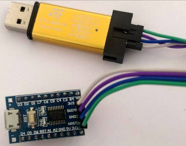
Make the connection and connect the device to your computer, the driver installation should begin automatically. You can use the device manager to ensure if your computer has discovered ST-LINK V2 correctly. You will also notice the test LED on the board blinking if this is the first time powering the board.
LED Blinking on STM8S103F3 using Arduino
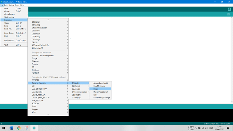
Now for a simple LED blinking, we can use the blink program from the example section. Follow File -> Example -> Generic_Example -> Basics -> Blink.
The complete program for blinking the onboard led is shown below-
void setup() {
  // initialize digital pin LED_BUILTIN as an output.
  pinMode(LED_BUILTIN, OUTPUT);
}
// the loop function runs over and over again forever
void loop() {
  digitalWrite(LED_BUILTIN, HIGH);   // turn the LED on (HIGH is the voltage level)
  delay(1000);                       // wait for a second
  digitalWrite(LED_BUILTIN, LOW);    // turn the LED off by making the voltage LOW
  delay(1000);                       // wait for a second
}
As you can see this is very similar to the Arduino blink program. To upload the program, make sure your board is connected via st-link v2 as discussed above and select the programmer as “ST-Link/V2” as shown below.
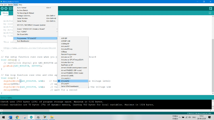
Note: Unlike Arduino boards, you do not have to select the right COM port for programming the board. You will use the COM port only for serial communication.
Once the COM port is selected, uploading the code is also very simple. Just press the upload button (encircled in red below) and the code will get compiled and uploaded to our board automatically.
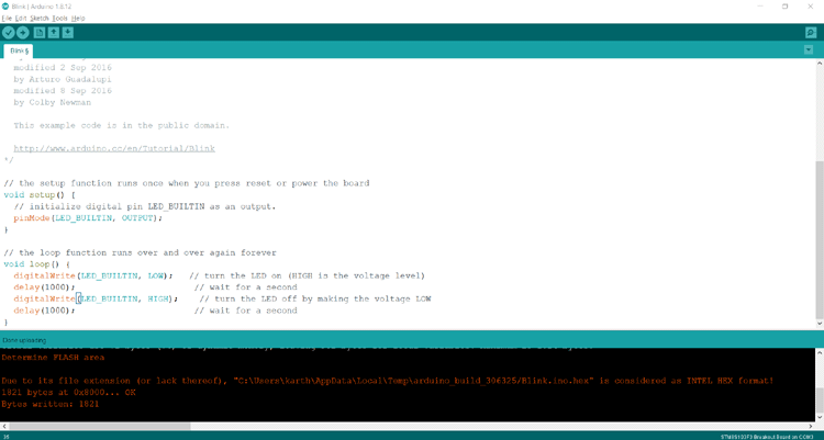
That is it, the program is uploaded directly to the board and you should see the on-board LED blinking. No external uploading software, no nothing. As easy as that. You can check out the video at the bottom of this page for the working.
Arduino Pin Mapping for STM8S103F3
If you want to proceed from here, you need to know how to address each pin on the STM8S103F3 Development board. The pin mapping can be understood from this image below-

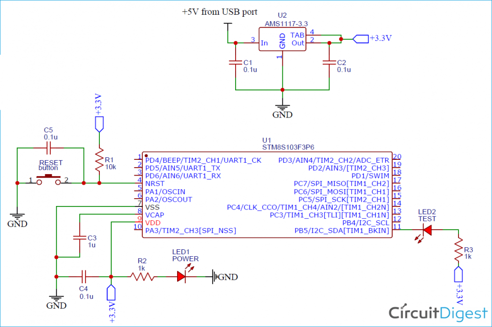
For example from the STM8S103F3 Board circuit diagram, we know that the on-board LED is connected to PB5. To address this pin on Arduino, we have to use 3, hence the program can be written as-
void setup() {
  // initialize digital pin LED_BUILTIN as an output.
  pinMode(3, OUTPUT);
}
// the loop function runs over and over again forever
void loop() {
  digitalWrite(3, LOW);   // turn the LED on (HIGH is the voltage level)
  delay(1000);                       // wait for a second
  digitalWrite(3, HIGH);    // turn the LED off by making the voltage LOW
  delay(1000);                       // wait for a second
}
Compiling SPL Libraries on Arduino IDE
As mentioned earlier, we can also use the SPL library on Arduino IDE. If you remember, in our previous STM8S GPIO tutorial, we wrote a code to blink the on-board LED and also an external LED using the push button. The same code with very few modifications can also be compiled on Arduino. The modified code is shown below.
#define Green_LED GPIOA, GPIO_PIN_3

void setup() {
GPIO_DeInit(GPIOA); //prepare Port A for working
GPIO_DeInit(GPIOB); // prepare Port B for working
//Declare PA2  as input pull up pin
GPIO_Init (GPIOA, GPIO_PIN_2, GPIO_MODE_IN_PU_IT);
//Declare PA3 as Push Pull Output pin
GPIO_Init (Green_LED, GPIO_MODE_OUT_PP_LOW_SLOW);
//Declare PB5 as push pull Output pin
GPIO_Init (GPIOB, GPIO_PIN_5, GPIO_MODE_OUT_PP_LOW_SLOW);
}
void loop() {
if (GPIO_ReadInputPin(GPIOA, GPIO_PIN_2)) //if button pressed
GPIO_WriteLow(Green_LED); //LED ON
else
GPIO_WriteHigh(Green_LED); //LED OFF
GPIO_WriteReverse(GPIOB,GPIO_PIN_5);
delay (100);
}
To conclude the Arduino IDE along with the Sduino is very good option if you want to jump start your development with STM8S. However, the platform is still under development and many Arduino libraries are yet to be supported. Still, if you wish to dig deep in and contribute to the development, it would be great. But, for the sake of learning, I will continue the tutorial series with STVD and cosmic C compiler.
Complete Project Code
/* MAIN.C file
 *
 * Copyright (c) 2002-2005 STMicroelectronics
 */

 #define Green_LED GPIOA, GPIO_PIN_3
 #include "STM8S.h"

void delay (int ms) //Function Definition
{
int i =0 ;
int j=0;
for (i=0; i<=ms; i++)
{
for (j=0; j<120; j++) // Nop = Fosc/4
_asm("nop"); //Perform no operation //assembly code
}
}

main()
{
GPIO_DeInit(GPIOA); //prepare Port A for working
GPIO_DeInit(GPIOB); // prepare Port B for working

//Declare PA2  as input pull up pin
GPIO_Init (GPIOA, GPIO_PIN_2, GPIO_MODE_IN_PU_IT);

//Declare PA3 as Push Pull Output pin
GPIO_Init (Green_LED, GPIO_MODE_OUT_PP_LOW_SLOW);

//Declare PB5 as push pull Output pin
GPIO_Init (GPIOB, GPIO_PIN_5, GPIO_MODE_OUT_PP_LOW_SLOW);

while (1)
{
if (GPIO_ReadInputPin(GPIOA, GPIO_PIN_2)) //if button pressed
GPIO_WriteLow(Green_LED); //LED ON
else
GPIO_WriteHigh(Green_LED); //LED OFF
GPIO_WriteReverse(GPIOB,GPIO_PIN_5);
delay (100);
}
}