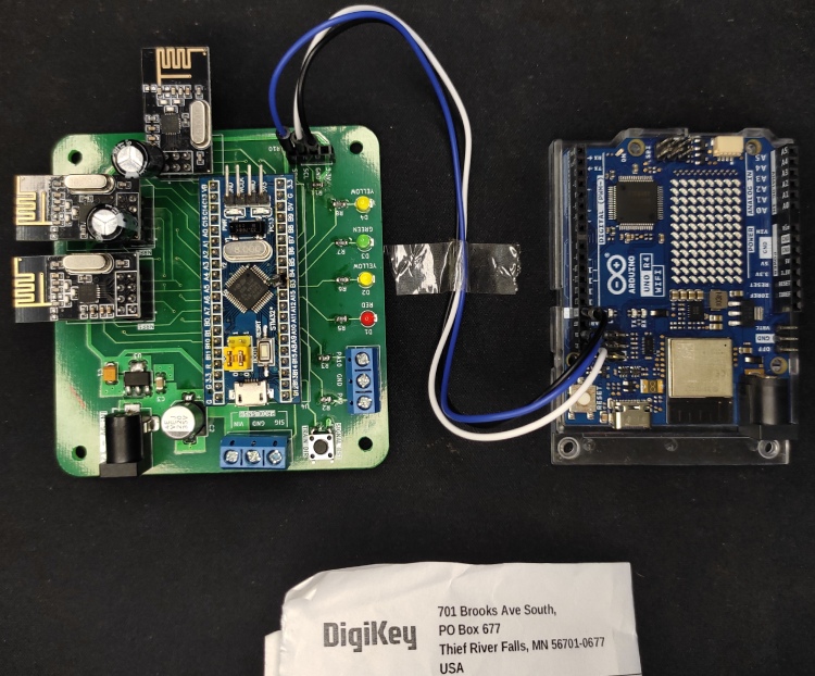
IMPACT STATEMENT
OTAPS (Open Train Accident Prevention System) is an open source train accident prevention system designed as a cost-effective alternative to TCAS (also known as KAVACH) used by the Indian Railways.
The Indian Railway has experienced a lot of accidents in the past few months. One of the primary reason for many such accidents is the absence of TCAS, as the cost of installation per kilometer of track is 5,000,000 INR [1] and per locomotive is around 7,000,000 INR [1].
OTAPS on the other hand has an installation cost of just 8000 INR per kilometer of track and 4000 INR per locomotive.
The best part about OTAPS is that it can be installed on routes that do not have any automatic signals, as it is capable of working independently. The power consumption during operation is under 1 watts. This makes it possible to simply power it from a solar panel and a battery, thereby eliminating the need for external electrical infrastructure.
Furthermore, a web interface has been implemented to display the status of the railway line to the station master. It displays information like axle counts, state of the next 4 signals as well as it allows for changing the state of the signal.
Components Required
1) Arduino UNO R4 Wi-Fi – 2 Pcs (* For the sake of demonstration, one will do)
2) M177 NRF24L01 2.4GHz Antenna Wireless Transceiver Module – 17 Pcs
3) AMS1117-3.3V, 1A, SOT-223 Voltage Regulator IC – 7 Pcs
4) 22 µF, 16 V, 1411, AVX-Surface Mount Tantalum Capacitor, (TAJB226K016RNJ) – 7 Pcs
5) 1UF, 50V, X5R, 10%, 1206 CERAMIC CAPACITOR (UMK316BJ105KD) – 7 Pcs
6) 220uF 35V Surface Mount Electrolytic Capacitor – 7 Pcs
7) 10uF 35V Electrolytic Capacitor – 17 Pcs
8) STM32 BluePill STM32F103C8T6 – 7 Pcs
9) KF301 3 Pin 5.08mm Pitch Screw Terminal Block – 14 Pcs
10) Tactile Switch-Tk-066-4 Pins 6X6 Smd – 7 Pcs
11) DC-005 5.5x2.1mm Female Barrel Jack Socket – 7 Pcs
12) DC-005 5.5x2.1mm Male Barrel Jack Socket – 7 Pcs
13) 2.54mm 1x40 Pin Female Header – 14 Pcs
14) 2.54mm 1x40 Pin Male Header – 3 Pcs
15) SSD1306 128 * 64px 0.96 Inch I2C OLED Display Module – 2 Pcs
16) 8mm NPN Inductive Proximity Sensor RM18 DC6~36V – 5 Pcs
17) 3mm THT Green LED – 5 Pcs
18) 3mm THT Yellow LED – 10 Pcs
19) 3mm THT Red LED – 5 Pcs
20) 0805 470 Ohm 1% 0.25W SMD Resistor (AC0805FR-7W470RL) – 48 Pcs
21) 0805 1K Ohm 1% 0.125W (RC0805FR-071KL) – 21 Pcs
22) Miscellaneous (Wires, Heat Shrink Tubes)
OVERVIEW
As eager as you might be to build this project, it is crucial to understand the working principles. OTAPS consists of three parts:
Signal Unit/Node
WEB UI
Locomotive Unit/Node
To see the full demonstration video, click on the YouTube Video below.
SIGNAL UNIT

As the name implies, they communicate the state of the railway line to the loco pilot. The signal units are placed on the railway tracks. The signal units communicate with other signal unit as well as the locomotive unit. The communication is done using NRF24 2.4GHz transceiver modules.
The signal unit transmits its state, as well the state of 3 [NOTE] signal units before (if present) and after (if present) it. So at any instance, the locomotive unit knows the signal state at the current signal unit and the 3 units after it.
In a nutshell, the signal units act as the 4 aspect automatic signals used by the Indian Railways with the added capability of transmitting their state as well the state of other signal units wirelessly. While also consuming very little power.
Each signal unit consists of two NRF24 modules. One of them is used to communicate with other signal units and the second one is used to communicate with the locomotive unit. They use an inductive NPN type proximity sensor to detect and count the axles of the train.
The first and the last signal units are paired with an Arduino UNO R4 Wi-Fi board, which is used to create a web dashboard for the station master. The web dashboard contains information regarding the signal states, number of axles, as well it allows changing the signal state.
NOTE:
3 is not a fixed limit, but since I could only make 5 signal units due to limited budget, I chose 3 as the sweet spot. This can be increased further with minimal changes.
SIGNAL UNIT INTERFACE

Power Input (6V - 12V)
Three NRF24 Transceiver module: One for communicating with the lower signal units, the other for communicating with higher signal units and the third one for communicating with the locomotive unit.
STM32 BluePill board: For processing the signal data, controlling the communication with other signal units, locomotive units and Arduino UNO R4 Wi-Fi.
4 LEDs to display the signal state.
Signal Reset Switch: To reset the signal state to Green.
Proximity Sensor connector.
Auxiliary port for future additions.
Arduino UNO R4 Wi-Fi for data transfer between the WEB interface and signal units (only used on 1st and nth(last) node).
WEB UI

The station master is in charge of maintaining a safe passage of trains. The WEB interface allows the station master to monitor and control the state of the signals. It is based on the Blynk platform. The Arduino UNO R4 WiFi from Digikey acts as a link between the web interface and the home signal unit.

WEB UI INTERFACE

LOCOMOTIVE UNIT

The locomotive unit, as the name implies, is fitted on the locomotive. It displays the state of next 4 signal units. It performs 3 operations:
Slowing the train, when approaching a yellow signal.
Applying brakes, when approaching a red signal.
Applying brakes, when two trains end up on the same track and are moving towards each other.
LOCOMOTIVE UNIT INTERFACE

Power Input (6V - 12V)
NRF24 Transceiver module: For communicating with the signal units.
STM32 BluePill board: For processing the signal data, controlling the communication with signal units, initiating actions such braking, speed limiting and displaying information on the OLED screen.
"Train Dir" switch: To toggle train direction between "upgoing" and "downgoing".
LEDs: The yellow leds D4 & D1 shows the train direction, if it's "upgoing" or "downgoing". When D4 is lit then the train is upgoing and when D1 is lit the train is downgoing.
Auxiliary I/O port.
OLED display to view the locomotive and signal status.
DISPLAY UI

COMMUNICATION PROTOCOL
The communication between signal units and between signal units and locomotive unit is done via NRF24 modules.
PAYLOAD FORMAT
The image below shows the contents of the payload.

The payload contains 8 bytes. The contents of each byte are described below:
1st byte: Source ID/transmitting node ID.
2nd byte: Destination ID/Receiving node ID.
Bytes 3–6 contain the signal data. 'C' is the node no of the signal node that transmitted the data. It is further elaborated with the help of an example below.
3rd byte: It contains the number of axles/wheels that passed the node that transmitted the data.
4th byte: The first 4 bits are the status flag, the purpose of the status flag is described in the status flag section. The last 4 bits of contain the data of the (C - 3)th node.
5th byte: First 4 bits represent the signal state of (C - 2)th node, and the last 4 bits represent the signal state of (C - 1)th node.
6thbyte: First 4 bits represent the signal state of (C)th node/ the node that transmitted the payload, and the last 4 bits represent the signal state of (C + 1)th node.
7th byte: First 4 bits represent the contains the signal state of (C + 2)th node, and the last 4 bits represent the signal state of (C + 3)th node.
8th byte: It is a 1's complement checksum for the payload.
EXAMPLE:
If '4' is the node no of the signal node that transmitted the data, then:
C = 4, state of the current node
C - 3 = 1, the state of 1st node
C - 2 = 2, the state of 2nd node
C - 1 = 3, the state of 3rd node
C + 1 = 5, the state of 5th node
C + 2 = 6, the state of 6th node
C + 3 = 7, the state of 7th node
STATUS FLAG
The contents of the status flag are described below:

Bit 7: Reserved.
Bit 6: Reserved.
Bit 5: Signal Reset (SR) when this bit is set, it indicates to the receiving signal node that it must set its signal to GREEN state. This bit is only used by the 1st and nth(last) signal node.
Bit 4: Node Ready (NR), when this bit is set, it indicates that the signal node that transmitted the payload is ready. This bit is 0 upon a startup, and 1 when the node is initialized. Check out the signal unit initialization section below for more information.
SIGNAL UNIT COMMUNICATION
The image below shows the communication between the signal nodes from a power up.

Let's number the nodes from left to right, starting from 1. So, node A is 1, B is 2 and E is 5. Every even numbered node acts as the master node, i.e, B and D are the master nodes. The continuous arrow represents the master payload and the dotted arrow represents the response of the slave to the master.
Each master node operates on a different channel to not interfere with other master nodes. The slave nodes change their operation channel based on the node they need to communicate with. Lowercase 'a' is the value of Node A, 'b' is the value of Node B, 'c' is the value of Node C and so on. The "Val" in the nodes, shows the signal values each node possess.
On startup (step 1), each node possesses its own value represented by the lowercase alphabet of the node name. The master sends a payload with its to the node before it (lower numbered node), and in response, the slave sends the payload with its signal value. The received value is stored in the signal data array.
In step 2, nodes A, B, C and D now posses their own signal value as well the signal value of the node they communicated with. The master nodes now send a payload to the slave nodes after it (higher numbered node). In response to the payload received, the slave nodes send a response consisting of the signal values possessed by them.
In step 3, the master nodes transmit data to the lower numbered slave nodes, i.e, nodes A and C. The "✓" above nodes A, C and D signify that these nodes are initialized/ready. This means that they have acquired the signal values from at most 3 nodes before (if available) and after (if available) them. The NR bit in the status flag of the payload of the initialized node will be set to 1 for all upcoming transmissions.
In step 4, the master nodes transmit data to the higher numbered slave nodes, i.e, nodes C and E. At step 4, all the nodes are ready as evident by the "✓". The NR bit in the status flag of the payload of the initialized node will be set to 1 for all upcoming transmissions. Step 4 marks the end of the initialization process.
Step 5 just shows the communications and the payload contents after the initialization process. This process of the mastering node alternating between communication between higher and lower numbered node continues.
LOCOMOTIVE UNIT COMMUNICATION
The image below shows the communication between the locomotive unit and the signal unit.

The picture above describes the communication between the locomotive unit and the signal unit. The locomotive unit and the signal unit operate at a different RF channel such that it does not interfere with the communication between the signal nodes. The state of the signal nodes are represented by the letters:
R = Red
Y = Yellow
DY = Double Yellow
G = Green
The locomotive unit initiates the communication with the signal unit by sending a packet "S?" inquiring about the state of the signal units. The locomotive packet contains the address of the signal unit. In response to the locomotive packet, the signal unit sends a packet as denoted by "S" in the picture above. The content of the signal unit packet has been described in the payload format section above.
Initially, the locomotive starts the communication with node A. Once it reaches node A, it switches to B, then C, D and at last E. When the locomotive reaches a signal node, the state of the signal node changes to Red. The locomotive unit uses this information to deduce that it has reached the signal node it had been communicating with, and makes a switch to the next signal node.
WEB INTERFACE AND SIGNAL UNITS

The Arduino UNO R4 WiFi acts as the bridge between the web interface and the signal units. The data transfer between the Arduino and the signal unit is done via I2C. The Arduino sends the data received from the web interface to the signal unit, and vice versa. The Arduino acts as the I2C master whereas the STM32 on the signal units acts as the slave.
The I2C payload from the Arduino is 2 bytes in length. The first byte contains the value of the signal reset button(either 1 or 0 ), and the second byte contains the value of the home signal button from the web interface.
The contents of the I2C payload from the signal unit is the same as that of the locomotive unit.
CIRCUIT DIAGRAM
This section delves over the wiring and the circuit diagram. The KiCAD files for this project is availabe at this GitHub repository. The project is divided into three schematics: signal unit wiring, locomotive unit wiring and the node schematic.
SIGNAL NODE


The signal node uses an NPN NO (Normally Open) proximity sensor to detect the axles of the train. The proximity sensor has three wire, Brown is VCC, Blue is Ground and Black is output. These wire are connected to the terminal block labelled "PROX_SNSR" on the Signal node PCB. BROWN connects to VIN, BLUE to GND and BLACK to SIG.
To create the web interface for the station master, an Arduino UNO R4 Wi-Fi from Digikey is utilised. The IIC pins of the Arduino UNO R4 Wi-Fi are connected to the SCL and SDA on the signal node labelled under "I2C" along with GND.
NOTE:
Arduino UNO R4 Wi-Fi must be connected to only first and the last (nth) signal node.
LOCOMOTIVE NODE

For the locomotive unit, the I2C port is connected to a SSD1306 128 * 64 OLED screen. The terminal block with the pin labelled PA8 connects to the PWM pin of the model train.
NOTE:
For demonstration, I am using a toy train modified a with a MOSFET drivers to drive the motor. You can use any other toy train of your choice. Since, I am using a toy train, a PWM signal is used to apply brakes and moderate the speed of the train. Please do note that, this PWM implementation of speed control is only for demonstration using the model train. The actual implementation for braking will have to altered for a real locomotive.
NODE

The picture above shows the schematic for the PCBs. Both the signal unit and the locomotive unit utilise the same PCB.
As it can seen in the schematic, it requires a lot of components. Manual, soldering each and every component will prove to be rather tedious and error prone, which is why I have created a PCB to ease the assembly process.
It won't be going over connection between the components, as it clearly visible on the schematic. Instead, I will be discussing the purpose of parts used in this schemaitc.
Starting from the top left corner of the schematic is the power supply section, it consists of the AMS1117 3.3V linear voltage regulator. Underneath the power supply section the "signal reset / train dir" switch. When using the PCBs for the signal units, this switch is used to reset the signal state to Green, whereas when it is configured as a locomotive unit, it toggles the train direction between upgoing and downgoing. To the right of the switch is the proximity sensor port. Underneath the "signal reset / train dir" switch, is the "IO" port, these ports are user confrigurable. Underneath the "IO" port, is the I2C port, which is either used to connect an OLED display in a locomotive unit, or the Arduino UNO R4 for first and last signal unit. The STM32 BluePill board governs the operation of the board, from controlling the communication between the signal units and locomotive units, to processing inputs from pheripherals and setting the signals. Underneath the BluePill, are the signal lights and to the right are the NRF24 transceiver modules.
ASSEMBLY
This section describes the assembly process for the signal and the locomotive unit.
COMPONENTS
1) Arduino UNO R4 Wi-Fi – 2 Pcs (* For the sake of demonstration, one will do)
2) M177 NRF24L01 2.4GHz Antenna Wireless Transceiver Module – 17 Pcs
3) AMS1117-3.3V, 1A, SOT-223 Voltage Regulator IC – 7 Pcs
4) 22 µF, 16 V, 1411, AVX-Surface Mount Tantalum Capacitor, (TAJB226K016RNJ) – 7 Pcs
5) 1UF, 50V, X5R, 10%, 1206 CERAMIC CAPACITOR (UMK316BJ105KD) – 7 Pcs
6) 220uF 35V Surface Mount Electrolytic Capacitor – 7 Pcs
7) 10uF 35V Electrolytic Capacitor – 17 Pcs
8) STM32 BluePill STM32F103C8T6 – 7 Pcs
9) KF301 3 Pin 5.08mm Pitch Screw Terminal Block – 14 Pcs
10) Tactile Switch-Tk-066-4 Pins 6X6 Smd – 7 Pcs
11) DC-005 5.5x2.1mm Female Barrel Jack Socket – 7 Pcs
12) DC-005 5.5x2.1mm Male Barrel Jack Socket – 7 Pcs
13) 2.54mm 1x40 Pin Female Header Socket – 14 Pcs
14) 2.54mm 1x40 Pin Male Header Socket – 3 Pcs
15) SSD1306 128 * 64px 0.96 Inch I2C OLED Display Module – 2 Pcs
16) Orange 8mm NPN Inductive Proximity Sensor RM18 DC6~36V – 5 Pcs
17) 3mm THT Green LED – 5 Pcs
18) 3mm THT Yellow LED – 10 Pcs
19) 3mm THT Red LED – 5 Pcs
20) 0805 470 Ohm 1% 0.25W SMD Resistor (AC0805FR-7W470RL) – 48 Pcs
21) 0805 1K Ohm 1% 0.125W (RC0805FR-071KL) – 21 Pcs
22) Miscellaneous (Wires, Heat Shrink Tubes)
Both the signal, and the locomotive unit utilise the same PCBs. The KiCAD files for this project can be found at this GitHub repository.


1) SIGNAL UNIT

The section shows the assembly steps for the signal units. We are going to start with assembling the power supply section first.
1) POWER SUPPLY
Start by soldering the low profile components first, such as the 22µF tantalum capacitor, AMS1117 3.3V linear voltage regulator and the 1µF ceramic capacitor.

Now, solder the 220µF electrolytic capacitor, and the female barrel jack. Although, I recommend leaving the THT components for the end.

2) RESISTORs
Solder the 1KΩ pull up resistors for the I2C port, signal reset switch and the proximity sensor input.


Solder the 470Ω series resistor for the LEDs, and the IO port.

3) SIGNAL RESET SWITCH

4) TERMINAL BLOCK
2 * 5mm pitch 3 pin terminal block for the proximity sensor, and the IO port.

5) 3MM SIGNAL LEDS
One Red, two Yellow and one Green 3mm signal LEDs.

6) HEADER PINS
2 * 20 pin 2.54mm female header pin for the BluePill dev board.

3 sets of 2 * 4 pin 2.54mm pitch female header for the NRF24 modules.

4 pin 2.54 mm female header pin for the I2C port.

7) PLACING THE MODULES

8) WIRING THE PROXMITY SENSOR
Connect the proximity sensor to the port labelled PROX_SNSR. Refer to the section SIGNAL NODE under the CIRCUIT DIAGRAM section for wiring.

9) WIRING ARDUINO UNO R4 WiFi
This section applies only to the 1st and last signal node. In this case, it is signal node 1 and signal node 5 as these are the home signals. SDA of the signal unit connects to SDA on the Arduino, SCL connects to SCL and GND of the signal unit connects to GND of the Arduino UNO R4 WiFi.


DONE! ASSEMBLED! CONGRATS, we have successfully assembled the signal unit. Now, as good as this may feel, let me bring you down by saying we need to assemble 5 of these. But that is only for demonstration, just 4 signal units can suffice to prove the working concept.

2) LOCOMOTIVE UNIT
This section describes the assembly process of the locomotive unit. Since both the signal, and the locomotive unit utilise the same PCBs, they have some overlap in the assembling process.
To assemble the locomotive unit, follow the assembly steps in the signal unit til step 6 with the exception that you may choose to eliminate the terminal block for the PROX_SNSR port, and the female headers for NRF2 and NRF3. The pull up resistors for I2C can be eliminated, as the OLED screen includes them.

1) OLED

2) PLACE THE MODULES

DONE! ASSEMBLED! Although, to demonstrate that it can prevent the collision between two trains, we will have to make two of these.

FIRMWARE
This section describes the firmware for the project. OTAPS consists of 3 parts: the signal unit, locomotive unit and the web interface. The operation of the signal unit and the locomotive unit is governed by the STM32, and the firmware for it written using CubeIDE and the HAL framework by STMicroelectronics. The web interface is based on the Blynk platform and is controlled by the Arduino UNO R4 WiFi.
The code for this project can be found at this GitHub repository. The firmware for the signal and the locomotive unit is well over 1200 lines. I won't be going over what each and every lines does, the code is commented well enough for that. Instead I will provide an oveview of the code, and explain the purpose of the files. The comments along with the explanation in this article should remove any ambiguity in understanding the code.
Please note that the code snippets here are for explanation purpose, and may not be upto date with the latest features and bug fixes. For the most recent updates, refer to the GitHub repository.
1) SIGNAL UNIT
This section goes over the firmware for the Signal Unit.
FIRMWARE
As with any CubeMx project, it generates a lot of files most of which are for pheripheral initialisation, interrupts call back and startup files. However the files that we will focusing on are config.h & config.c, payload. h, nodes.h & nodes.c, and main.h & main.c.
config.h & config.c: These are used to configure the node number, addresses, node ID, RF channel, communication data rate and power levels. I will get back to when during the programming section.
#include "config.h"
const uint8_t THIS_NODE_NUM = 4;
const uint8_t TOTAL_NO_OF_NODES = 5;
// Node addresses
const uint8_t THIS_NODE_ADDRESS[5] = "NRF44";
const uint8_t NEXT_NODE_ADDRESS[5] = "NRF54";
const uint8_t *PREV_NODE_ADDRESS = THIS_NODE_ADDRESS;
const uint8_t *LOCOMOTIVE_NODE_ADDRESS = THIS_NODE_ADDRESS;
// Node ID
// for the sake of simplicity, node number will the node ID
const uint8_t THIS_NODE_ID = THIS_NODE_NUM;
const uint8_t PREV_NODE_ID = THIS_NODE_NUM - 1;
const uint8_t NEXT_NODE_ID = THIS_NODE_NUM + 1;
const uint8_t LOCOMOTIVE_NODE_ID = 0x6E;
// RF Channel
const uint8_t NRF24_LOWER_NODE_RF_CHANNEL = THIS_NODE_NUM;
const uint8_t NRF24_HIGHER_NODE_RF_CHANNEL = THIS_NODE_NUM + 1;
const uint8_t NRF24_LOCOMOTIVE_NODE_RF_CHANNEL = 110;
const uint8_t NRF24_RF_CHANNEL_MIN = 1, NRF24_RF_CHANNEL_MAX = 105;
// NRF24 module config
const uint8_t NRF24_TX_PWR = nRF24_TXPWR_18dBm; // one of nRF24_TXPWR_xx values
const uint8_t NRF24_DATA_RATE = nRF24_DR_250kbps; // one of nRF24_DR_xx values
const uint8_t NRF24_AUTO_RETRY_DELAY = nRF24_ARD_2250us; // one of nRF24_ARD_xx values
const uint8_t NRF24_AUTO_RETRY_COUNT = 10; // from 0 - 15
const unsigned long TX_INTERVAL = 166, SW_SAMPLING_INTERVAL = 15;
paylaod.h: This files contains information regarding the payload format.
#ifndef INC_PAYLOAD_H_
#define INC_PAYLOAD_H_
#define IIC_RX_PAYLOAD_LENGTH 2
#define IIC_SIGNAL_RESET_INDEX 0
#define IIC_HOME_SIGNAL_STATE_INDEX 1
#define PAYLOAD_LENGTH 8
#define SOURCE_ID_INDEX 0
#define DESTINATION_ID_INDEX 1
#define AXLE_COUNT_INDEX 2
#define STATUS_P3_NODE_INDEX 3 // index for status flag and 3rd node before the current node
#define P2_P1_NODE_INDEX 4 // index for 2nd and 1st node before the current node
#define C_N1_NODE_INDEX 5 // index for current node and next node after current node
#define N2_N3_NODE_INDEX 6 // index for 2nd and 3rd node after the current node
#define CHECKSUM_INDEX 7
#define __NODE_READY_BIT_INDEX 4
#define __SIGNAL_RESET_BIT_INDEX 5
#define __GET_SIGNAL_RESET_BIT_STATE(BYTE) ((BYTE & (1 << __SIGNAL_RESET_BIT_INDEX)) >> __SIGNAL_RESET_BIT_INDEX)
#define __GET_NODE_READY_BIT_STATE(BYTE) ((BYTE & (1 << __NODE_READY_BIT_INDEX)) >> __NODE_READY_BIT_INDEX)
#endif /* INC_PAYLOAD_H_ */
nodes.h & nodes.c: These files contains the supporting functions for operation such as initliatisation of the signal nodes, extracting, verifying and updating the payload as well as updating the signal state.
#ifndef INC_NODES_H_
#define INC_NODES_H_
#include "main.h"
#include "nrf24.h"
#include "config.h"
#include "payload.h"
#include <stdio.h>
#include <stdbool.h>
#include <string.h>
typedef enum
{
SIGNAL_NOT_KNOWN = 0, RED, YELLOW, DOUBLE_YELLOW, GREEN
} Signal;
typedef struct signalstate
{
Signal state;
struct signalstate *next;
} SignalState;
typedef enum
{
TRAIN_DIR_NOT_KNOWN = 0, TO_LOWER_NODE, TO_HIGHER_NODE
} TrainDirection;
typedef struct node
{
struct node *prev;
struct node *next;
Signal signal;
uint8_t nodeID;
uint8_t nodeReady;
uint8_t signalReset;
uint8_t axleCount;
uint8_t signalData[3];
} Nodes;
typedef struct
{
uint8_t receivePayload[PAYLOAD_LENGTH];
uint8_t transmitPayload[PAYLOAD_LENGTH];
} Payload;
extern Nodes thisNode;
extern SignalState red, doubleYellow, yellow, green;
extern volatile uint16_t axleCounter;
extern volatile SignalState *currentSignalState;
extern volatile TrainDirection trainDir;
void signalStateInit(void);
bool isNodeReady(void);
bool isPayLoadValid(Payload *p, uint8_t communicatingNodeID);
void extractPayloadData(Payload *p, uint8_t communicatingNodeID);
void updateTxPayload(Payload *p, uint8_t communicatingNodeID);
void updateSignalState(void);
void setSignalLeds(void);
#endif /* INC_NODES_H_ */
main.h & main.c:These files contains the definition for the pins, code for pheripheral initialization, intializing the nrf modules and managing communication with the nodes. The flow chart below describes the program flow.
int main(void)
{
/* USER CODE BEGIN 1 */
NodeType nodeType = (THIS_NODE_NUM % 2) ? SLAVE : MASTER;
uint8_t nrf24OperationMode = nRF24_MODE_RX;
/* USER CODE END 1 */
/* MCU Configuration--------------------------------------------------------*/
/* Reset of all peripherals, Initializes the Flash interface and the Systick. */
HAL_Init();
/* USER CODE BEGIN Init */
/* USER CODE END Init */
/* Configure the system clock */
SystemClock_Config();
/* USER CODE BEGIN SysInit */
/* USER CODE END SysInit */
/* Initialize all configured peripherals */
MX_GPIO_Init();
MX_I2C1_Init();
MX_SPI1_Init();
/* USER CODE BEGIN 2 */
signalStateInit();
// if node type is master then set nrf module into PTX mode and start communication with previous node first
// else set nrf module into PRX and start communication with the next node
if (nodeType == MASTER)
{
nrf24OperationMode = nRF24_MODE_TX;
if (thisNode.prev != NULL)
currentComNode = &prevSignalNode;
else
currentComNode = &nextSignalNode;
} else
{
nrf24OperationMode = nRF24_MODE_RX;
if (thisNode.next != NULL)
currentComNode = &nextSignalNode;
else
currentComNode = &prevSignalNode;
}
// initialize the nrf module for lower signal node and prev signal node structure (if present)
if (thisNode.prev != NULL)
{
prevSignalNode.nrf = &nrf1;
prevSignalNode.pl = &prevNodePayload;
if (thisNode.next != NULL)
prevSignalNode.next = &nextSignalNode;
prevSignalNode.nodeID = thisNode.prev->nodeID;
radioInit(prevSignalNode.nrf, PREV_NODE_ADDRESS, NRF24_LOWER_NODE_RF_CHANNEL, nrf24OperationMode);
}
// initialize the nrf module for lower signal node and next signal node structure
if (thisNode.next != NULL)
{
nextSignalNode.nrf = &nrf2;
nextSignalNode.pl = &nextNodePayload;
if (thisNode.prev != NULL)
nextSignalNode.next = &prevSignalNode;
nextSignalNode.nodeID = thisNode.next->nodeID;
radioInit(nextSignalNode.nrf, NEXT_NODE_ADDRESS, NRF24_HIGHER_NODE_RF_CHANNEL, nrf24OperationMode);
}
locomotiveNode.nrf = &nrf3;
locomotiveNode.pl = &locomotiveNodePayload;
locomotiveNode.next = NULL;
radioInit(locomotiveNode.nrf, LOCOMOTIVE_NODE_ADDRESS, NRF24_LOCOMOTIVE_NODE_RF_CHANNEL, nRF24_MODE_RX);
/* USER CODE END 2 */
/* Infinite loop */
/* USER CODE BEGIN WHILE */
// if a previous node exist and this node is a slave
// then write the ack payload and set the respective nrf module in RX mode
if (thisNode.prev != NULL)
{
updateTxPayload(prevSignalNode.pl, thisNode.prev->nodeID);
if (nrf24OperationMode == nRF24_MODE_RX)
{
// update ack payload
nRF24_WriteAckPayload(prevSignalNode.nrf, nRF24_PIPE0, (char*) prevSignalNode.pl->transmitPayload,
PAYLOAD_LENGTH);
// start receiving when configured as PRX
nRF24_CE_H(prevSignalNode.nrf);
}
}
// if a next node exist and this node is a slave
// then write the ack payload and set the respective nrf module in RX mode
if (thisNode.next != NULL)
{
updateTxPayload(nextSignalNode.pl, thisNode.next->nodeID);
if (nrf24OperationMode == nRF24_MODE_RX)
{
// update ack payload
nRF24_WriteAckPayload(nextSignalNode.nrf, nRF24_PIPE0, (char*) nextSignalNode.pl->transmitPayload,
PAYLOAD_LENGTH);
// start receiving when configured as PRX
nRF24_CE_H(nextSignalNode.nrf);
}
}
// initializing the locomotive nrf module
updateTxPayload(locomotiveNode.pl, LOCOMOTIVE_NODE_ID);
nRF24_WriteAckPayload(locomotiveNode.nrf, nRF24_PIPE0, (char*) locomotiveNode.pl->transmitPayload, PAYLOAD_LENGTH);
// write ack payload
nRF24_CE_H(locomotiveNode.nrf); // start receiving
// enable i2c only for first and last node, that is the home signals
if (THIS_NODE_NUM == 1 || THIS_NODE_NUM == TOTAL_NO_OF_NODES)
{
HAL_I2C_Slave_Receive_IT(&hi2c1, i2cPayload.receivePayload, IIC_RX_PAYLOAD_LENGTH);
}
while (1)
{
// IICSignalReset and homeSignalState are modified in the i2c IRQ,
// and the only first and last node have i2c enabled
if (THIS_NODE_NUM == 1 || THIS_NODE_NUM == TOTAL_NO_OF_NODES)
{
thisNode.signalReset = IICSignalReset;
switch (homeSignalState)
{
case RED:
currentSignalState = &red;
break;
case GREEN:
currentSignalState = &green;
break;
default:
break;
}
}
// reset axle counter and signal state
if ((HAL_GPIO_ReadPin(SIGNAL_RST_SW_GPIO_Port, SIGNAL_RST_SW_Pin) == GPIO_PIN_RESET) || thisNode.signalReset)
{
axleCounter = 0;
currentSignalState = &green;
trainDir = TRAIN_DIR_NOT_KNOWN;
}
switch (nodeType)
{
case MASTER:
masterNode();
break;
case SLAVE:
slaveNode();
break;
default:
break;
}
/* USER CODE END WHILE */
/* USER CODE BEGIN 3 */
}
/* USER CODE END 3 */
}
OPERATION FLOW CHART
This flow chart shows the program flow for the signal units.
MAIN PROGRAM FLOW

MASTER NODE OPERATION

SLAVE NODE OPERATION

PROGRAMMING
To program the signal units, the config.c file has to be altered.
#include "config.h"
const uint8_t THIS_NODE_NUM = 1;
const uint8_t TOTAL_NO_OF_NODES = 5;
// Node addresses
const uint8_t THIS_NODE_ADDRESS[5] = "NRF14";
const uint8_t NEXT_NODE_ADDRESS[5] = "NRF24";
const uint8_t *PREV_NODE_ADDRESS = THIS_NODE_ADDRESS;
const uint8_t *LOCOMOTIVE_NODE_ADDRESS = THIS_NODE_ADDRESS;
// Node ID
// for the sake of simplicity, node number will the node ID
const uint8_t THIS_NODE_ID = THIS_NODE_NUM;
const uint8_t PREV_NODE_ID = THIS_NODE_NUM - 1;
const uint8_t NEXT_NODE_ID = THIS_NODE_NUM + 1;
const uint8_t LOCOMOTIVE_NODE_ID = 0x6E;
// RF Channel
const uint8_t NRF24_LOWER_NODE_RF_CHANNEL = THIS_NODE_NUM;
const uint8_t NRF24_HIGHER_NODE_RF_CHANNEL = THIS_NODE_NUM + 1;
const uint8_t NRF24_LOCOMOTIVE_NODE_RF_CHANNEL = 110;
const uint8_t NRF24_RF_CHANNEL_MIN = 1, NRF24_RF_CHANNEL_MAX = 105;
// NRF24 module config
const uint8_t NRF24_TX_PWR = nRF24_TXPWR_18dBm; // one of nRF24_TXPWR_xx values
const uint8_t NRF24_DATA_RATE = nRF24_DR_250kbps; // one of nRF24_DR_xx values
const uint8_t NRF24_AUTO_RETRY_DELAY = nRF24_ARD_2250us; // one of nRF24_ARD_xx values
const uint8_t NRF24_AUTO_RETRY_COUNT = 10; // from 0 - 15
const unsigned long TX_INTERVAL = 166, SW_SAMPLING_INTERVAL = 15;
Set TOTAL_NO_OF_NODES to the number of signal unit.
Set THIS_NODE_NUM is the number assigned to the signal unit you are programming. For example, the THIS_NODE_NUM = 1 for the first signal unit, 2 for the second and so on.
THIS_NODE_ADDRESS & NEXT_NODE_ADDRESS are the 5 byte address for the nrf modules communicating with the previous and next node respectively. One thing to keep in mind is that the value of THIS_NODE_ADDRESS of the signal unit you are programming will be the NEXT_NODE_ADDRESS of the previous signal unit. For example: if NEXT_NODE_ADDRESS of the first signal unit is "NRF24", then THIS_NODE_ADDRESS of the second signal unit will be "NRF24". Similarily, if NEXT_NODE_ADDRESS of the second signal unit is "NRF34", then THIS_NODE_ADDRESS of the third signal unit will be "NRF34".
You also have the option for changing the node IDs, however for the sake of simiplicity, I have decided to set the node IDs to be THIS_NODE_NUM for the signal units. Same with the RF channels.
2) LOCOMOTIVE UNIT
This section goes over the firmware for this project.
FIRMWARE
As with any CubeMx project, it generates a lot of files most of which are for pheripheral initialisation, interrupts call back and startup files. However the files that we will focusing on are config.h & config.c, payload. h, locomotive.h & locomotive.c, ui.h & ui.c and main.h & main.c.
config.h & config.c: These are used to configure the number of nodes, addresses, node ID, RF channel, communication data rate and power levels.
#include "config.h"
const uint8_t TOTAL_NO_OF_NODES = 5;
const uint8_t LOCOMOTIVE_NODE_ID = 0x6E;
const uint8_t NODE_IDS[] = { 1, 2, 3, 4, 5 };
const uint8_t NODE_ADDRESS[][5] = { "NRF14", "NRF24", "NRF34", "NRF44", "NRF54" };
// NRF24 module config
const uint8_t NRF24_TX_PWR = nRF24_TXPWR_18dBm; // one of nRF24_TXPWR_xx values
const uint8_t NRF24_DATA_RATE = nRF24_DR_250kbps; // one of nRF24_DR_xx values
const uint8_t NRF24_AUTO_RETRY_DELAY = nRF24_ARD_2250us; // one of nRF24_ARD_xx values
const uint8_t NRF24_AUTO_RETRY_COUNT = 10; // from 0 - 15
const uint8_t RF_CHANNEL = 110; // from 1 - 125
const uint16_t MAX_PWM_VAL = 400;
const unsigned long TX_INTERVAL = 200, SW_SAMPLING_INTERVAL = 15;
paylaod.h: This files contains information regarding the payload format.
#ifndef INC_PAYLOAD_H_
#define INC_PAYLOAD_H_
#define PAYLOAD_LENGTH 8
#define LOCOMOTIVE_PAYLOAD_LENGTH 2
#define SOURCE_ID_INDEX 0
#define DESTINATION_ID_INDEX 1
#define AXLE_COUNT_INDEX 2
#define STATUS_P3_NODE_INDEX 3 // index for status flag and 3rd node before the current node
#define P2_P1_NODE_INDEX 4 // index for 2nd and 1st node before the current node
#define C_N1_NODE_INDEX 5 // index for current node and next node after current node
#define N2_N3_NODE_INDEX 6 // index for 2nd and 3rd node after the current node
#define CHECKSUM_INDEX 7
#define __NODE_READY_BIT_INDEX 4
#define __SIGNAL_RESET_BIT_INDEX 5
#define __GET_SIGNAL_RESET_BIT_STATE(BYTE) ((BYTE & (1 << __SIGNAL_RESET_BIT_INDEX)) >> __SIGNAL_RESET_BIT_INDEX)
#define __GET_NODE_READY_BIT_STATE(BYTE) ((BYTE & (1 << __NODE_READY_BIT_INDEX)) >> __NODE_READY_BIT_INDEX)
#endif /* INC_PAYLOAD_H_ */
locomotive.h & locomotive.c: These files contain datatypes and supporting functions for validating and extracting the received payload, and updating the locomotive state.
#include "locomotive.h"
/*
* @brief Checks if payload is valid
*
* @param loco pointer to Locomotive object
* @param p pointer to Payload object
*
* @return bool payload valid
* - true payload is valid
* - false payload is invalid
*/
bool isPayLoadValid(Locomotive *loco, Payload *p)
{
// validate if payload received from current node
if (p->receivePayload[SOURCE_ID_INDEX] != loco->comNodeID
|| p->receivePayload[DESTINATION_ID_INDEX] != loco->id)
return false;
unsigned short sum = 0;
// validate checksum
for (uint8_t i = SOURCE_ID_INDEX; i < CHECKSUM_INDEX; i++)
{
sum += p->receivePayload[i];
sum += (sum >> 8); // one`s complement addition
}
// for a correct payload, sum + the received checksum should be equal to 255
if (((sum + p->receivePayload[CHECKSUM_INDEX]) & 0xFF) != 0xFF)
return false;
return true;
}
/**
* @brief Extracts the payload data into the respective Node object
*
* @param loco pointer to Locomotive object
* @param p pointer to Payload object
*
* @return None
*/
void extractPayloadData(Locomotive *loco, Payload *p)
{
uint8_t temp;
temp = p->receivePayload[STATUS_P3_NODE_INDEX];
loco->isComNodeReady = __GET_NODE_READY_BIT_STATE(temp);
switch (loco->dir) {
case TO_HIGHER_NODE:
temp = p->receivePayload[C_N1_NODE_INDEX];
loco->signalData[1] = (Signal)(temp & 0x0F);// signal state of the first node after the next node
loco->signalData[0] = (Signal)(temp >> 4); // signal state of the next node, i.e, the node that transmitted the data
temp = p->receivePayload[N2_N3_NODE_INDEX];
loco->signalData[3] = (Signal)(temp & 0x0F);// signal state of the third node after the next node
loco->signalData[2] = (Signal)(temp >> 4); // signal state of the second node after next node
break;
case TO_LOWER_NODE:
temp = p->receivePayload[C_N1_NODE_INDEX];
loco->signalData[0] = (Signal)(temp >> 4); // signal state of the previous node, i.e, the node that transmitted the data
temp = p->receivePayload[P2_P1_NODE_INDEX];
loco->signalData[1] = (Signal)(temp & 0x0F); // signal state of the first node after the previous node
loco->signalData[2] = (Signal)(temp >> 4); // signal state of the second node after previous node
temp = p->receivePayload[STATUS_P3_NODE_INDEX];
loco->signalData[3] = (Signal)(temp & 0x0F);// signal state of the third node after previous node
break;
default:
break;
}
}
/**
* @brief updates locomotive and line state
*
* @param loco pointer to Locomotive object
*
* @return None
*/
void updateLocomotiveState(Locomotive *loco)
{
switch (loco->signalData[0])
{
case GREEN:
loco->state = GO;
loco->line = CLEAR;
break;
case DOUBLE_YELLOW:
loco->state = GO;
loco->line = BLOCK;
break;
case YELLOW:
loco->state = SLOW_DOWN;
loco->line = BLOCK;
break;
case RED:
loco->state = STOP;
loco->line = BLOCK;
break;
default:
break;
}
// search for RED signal
uint8_t *ptr = (uint8_t*) memchr(loco->signalData, RED, NO_OF_NODES_TO_MONITOR + 1);
uint8_t index = 0;
if (ptr != NULL)
{
// get array index at which RED signal is found
index = ptr - loco->signalData;
switch (index)
{
case 0:
loco->state = STOP;
loco->line = BLOCK;
break;
case 1:
// train incoming
if (loco->signalData[2] != GREEN && loco->signalData[2] != SIGNAL_NOT_KNOWN)
{
loco->state = STOP;
loco->line = BLOCK;
} else
{
loco->state = SLOW_DOWN;
}
break;
case 2:
// train incoming
if (loco->signalData[3] != GREEN && loco->signalData[3] != SIGNAL_NOT_KNOWN)
{
loco->state = STOP;
loco->line = BLOCK;
} else
{
loco->state = SLOW_DOWN;
}
break;
default:
break;
}
}
}
ui.h & ui.c: These files contains function to create initialise the OLED display and update the UI based on the locomotive state.
#include "ui.h"
SSD1306 oled;
uint8_t frameBuffer[GET_SCREEN_BUFFER_SIZE(SSD1306_WIDTH, SSD1306_HEIGHT)];
static void centerCursor(SSD1306 *oled, uint8_t x1, uint8_t y1, uint8_t x2, uint8_t y2, uint8_t noOfCharacter, uint8_t fontWidth, uint8_t fontHeight)
{
float midX = (x2 - x1) / 2.00;
float midY = (y2 - y1) / 2.00;
float charCenterX = (fontWidth * noOfCharacter) / 2.00;
float charCenterY = fontHeight / 2.00;
oled->ssd1306_t.CurrentX = x1 + roundf((midX - charCenterX) + 1);
oled->ssd1306_t.CurrentY = y1 + roundf((midY - charCenterY)) + 1;
}
void UI_Init(SSD1306 *oled)
{
SSD1306_Init(oled, &hi2c1, 128, 64, 0x3C, frameBuffer, sizeof(frameBuffer));
Oled_Init(oled);
}
void updateUI(SSD1306 *oled, Locomotive *loco)
{
// creating table for node and loco state
Oled_DrawRectangle(oled, 0, 0, 61, 40, White);
Oled_DrawRectangle(oled, 61, 0, 124, 40, White);
Oled_Line(oled, 0, 12, 124, 12, White);
// NODE
Oled_SetCursor(oled, 18, 3);
Oled_WriteString(oled, "NODE", Font_6x8, White);
Oled_SetCursor(oled, 4, 15);
Oled_WriteString(oled, "NO :", Font_6x8, White);
Oled_WriteChar(oled, '0' + loco->comNodeNo, Font_6x8, White);
Oled_SetCursor(oled, 4, 27);
Oled_WriteString(oled, "RDY :", Font_6x8, White);
Oled_WriteString(oled, loco->isComNodeReady ? "YES" : "NO ", Font_6x8, White);
// LOCO
Oled_SetCursor(oled, 78, 3);
Oled_WriteString(oled, "STATE", Font_6x8, White);
Oled_SetCursor(oled, 65, 15);
Oled_WriteString(oled, "LOCO:", Font_6x8, White);
switch (loco->state)
{
case STOP:
Oled_WriteString(oled, "STOP", Font_6x8, White);
break;
case SLOW_DOWN:
Oled_WriteString(oled, "BRK ", Font_6x8, White);
break;
case GO:
Oled_WriteString(oled, "GO ", Font_6x8, White);
break;
default:
break;
}
Oled_SetCursor(oled, 65, 27);
Oled_WriteString(oled, "LINE:", Font_6x8, White);
// print line state
switch (loco->line)
{
case CLEAR:
Oled_WriteString(oled, "CLR", Font_6x8, White);
break;
case BLOCK:
Oled_WriteString(oled, "BLK", Font_6x8, White);
break;
default:
Oled_WriteString(oled, "---", Font_6x8, White);
break;
}
// // drawing rectangles for the signal state
// for (size_t x1 = 0, x2 = 31; x2 <= oled.width; x1 += 31, x2 += 31)
// {
// if (x1 < 93)
// {
// Oled_DrawRectangle(oled, x1, 43, x2, 63, White);
// }
// else
// {
// Oled_FillRectangle(oled, x1, 43, x2, 63, White);
// }
// }
// print the signal states
for (size_t i = 0, x1 = 0, x2 = 31; i < sizeof(loco->signalData) && x2 <= oled->width; i++, x1 += 31, x2 += 31)
{
switch (loco->signalData[i])
{
case GREEN:
Oled_FillRectangle(oled, x1, 43, x2, 63, Black);
Oled_DrawRectangle(oled, x1, 43, x2, 63, White);
centerCursor(oled, x1, 43, x2, 63, 1, 11, 18);
Oled_WriteChar(oled, 'G', Font_11x18, White);
break;
case DOUBLE_YELLOW:
Oled_FillRectangle(oled, x1, 43, x2, 63, Black);
Oled_DrawRectangle(oled, x1, 43, x2, 63, White);
centerCursor(oled, x1, 43, x2, 63, 2, 11, 18);
Oled_WriteString(oled, "DY", Font_11x18, White);
break;
case YELLOW:
Oled_FillRectangle(oled, x1, 43, x2, 63, Black);
Oled_DrawRectangle(oled, x1, 43, x2, 63, White);
centerCursor(oled, x1, 43, x2, 63, 1, 11, 18);
Oled_WriteChar(oled, 'Y', Font_11x18, White);
break;
case RED:
Oled_FillRectangle(oled, x1, 43, x2, 63, White);
centerCursor(oled, x1, 43, x2, 63, 1, 11, 18);
Oled_WriteChar(oled, 'R', Font_11x18, Black);
break;
default:
Oled_FillRectangle(oled, x1, 43, x2, 63, Black);
Oled_DrawRectangle(oled, x1, 43, x2, 63, White);
centerCursor(oled, x1, 43, x2, 63, 1, 11, 18);
Oled_WriteChar(oled, 'X', Font_11x18, White);
break;
}
}
Oled_UpdateScreen(oled);
}
main.h & main.c: These files contains the definition for the pins, code for pheripheral initialization, intializing the nrf modules, managing communication with the singal nodes, updating the UI and the locomotive state. The flow chart in the next section describes the program flow.
int main(void)
{
/* USER CODE BEGIN 1 */
/* USER CODE END 1 */
/* MCU Configuration--------------------------------------------------------*/
/* Reset of all peripherals, Initializes the Flash interface and the Systick. */
HAL_Init();
/* USER CODE BEGIN Init */
/* USER CODE END Init */
/* Configure the system clock */
SystemClock_Config();
/* USER CODE BEGIN SysInit */
/* USER CODE END SysInit */
/* Initialize all configured peripherals */
MX_GPIO_Init();
MX_I2C1_Init();
MX_SPI1_Init();
MX_TIM1_Init();
/* USER CODE BEGIN 2 */
locomotive.id = LOCOMOTIVE_NODE_ID;
locomotive.dir = TO_HIGHER_NODE;
locomotive.comNodeNo = 1;
locomotive.comNodeID = NODE_IDS[locomotive.comNodeNo - 1];
nRF24_Init(&nrf24);
nRF24_SetAddrWidth(&nrf24, 5);
nRF24_SetRFChannel(&nrf24, RF_CHANNEL);
nRF24_SetDataRate(&nrf24, NRF24_DATA_RATE);
nRF24_SetCRCScheme(&nrf24, nRF24_CRC_2byte);
nRF24_SetTXPower(&nrf24, NRF24_TX_PWR);
nRF24_SetAutoRetr(&nrf24, NRF24_AUTO_RETRY_DELAY, NRF24_AUTO_RETRY_COUNT);
nRF24_EnableAA(&nrf24, nRF24_PIPE0);
nRF24_SetOperationalMode(&nrf24, nRF24_MODE_TX);
nRF24_SetDynamicPayloadLength(&nrf24, nRF24_DPL_ON);
nRF24_SetPayloadWithAck(&nrf24, 1);
nRF24_SetPowerMode(&nrf24, nRF24_PWR_UP);
/* USER CODE END 2 */
/* Infinite loop */
/* USER CODE BEGIN WHILE */
UI_Init(&display);
updateUI(&display, &locomotive);
HAL_GPIO_WritePin(LED_YELLOW1_GPIO_Port, LED_YELLOW1_Pin, GPIO_PIN_RESET);
HAL_GPIO_WritePin(LED_YELLOW1_GPIO_Port, LED_YELLOW2_Pin, GPIO_PIN_SET);
while (1)
{
/* USER CODE END WHILE */
locomotiveOperation();
/* USER CODE BEGIN 3 */
}
/* USER CODE END 3 */
}
OPERATION FLOW CHART
This section shows the program flow diagram for the locomotive unit.

PROGRAMMING
To program the locomotive units, you need to alter the contents fo the config.c file.
#include "config.h"
const uint8_t TOTAL_NO_OF_NODES = 5;
const uint8_t LOCOMOTIVE_NODE_ID = 0x6E;
const uint8_t NODE_IDS[] = { 1, 2, 3, 4, 5 };
const uint8_t NODE_ADDRESS[][5] = { "NRF14", "NRF24", "NRF34", "NRF44", "NRF54" };
// NRF24 module config
const uint8_t NRF24_TX_PWR = nRF24_TXPWR_18dBm; // one of nRF24_TXPWR_xx values
const uint8_t NRF24_DATA_RATE = nRF24_DR_250kbps; // one of nRF24_DR_xx values
const uint8_t NRF24_AUTO_RETRY_DELAY = nRF24_ARD_2250us; // one of nRF24_ARD_xx values
const uint8_t NRF24_AUTO_RETRY_COUNT = 10; // from 0 - 15
const uint8_t RF_CHANNEL = 110; // from 1 - 125
const uint16_t MAX_PWM_VAL = 400;
const unsigned long TX_INTERVAL = 100, SW_SAMPLING_INTERVAL = 15;
Set TOTAL_NO_OF_NODES to the number of signal units, i.e, to the same value of TOTAL_NO_OF_NODES in the config.c file for the signal units.
Set LOCOMOTIVE_NODE_ID to the same value of LOCOMOTIVE_NODE_ID in the config.c file for the signal units.
NODE_IDS[] conatins the value of THIS_NODE_ID in the config.c file of the signal units. The order of contents of NODE_IDS[] starts from the THIS_NODE_ID of the first signal unit to the THIS_NODE_ID of the nth signal unit.
NODE_ADDRESS[][5] contains the value of THIS_NODE_ADDRESS in the config.c file of the signal units. The order of contents of NODE_ADDRESS[][5] starts from the THIS_NODE_ADDRESS of the first signal unit to the THIS_NODE_ADDRESS of the nth signal unit.
3) WEB UI
This section describes the firmware for the Arduinu UNO R4 and the Blynk setup.
FIRMWARE
The key files of focus are config.h, blynkCredentials.h, wifiCredentials.h and webUI.ino.
config.h: This file contains the payload format, I2C address, web page update interval and signal node IDs.

wifiCredentials.h: This file contains the WiFi SSID and password.

blynkCredentials.h: This file contains the blynk template ID, template name and auth token.

webUI.ino: This file contains the initialisation of I2C and blynk, and operation code for communicating with signal units and the blynk web page for extracting and updating the data. The flow chart in the next section describes the program flow.

OPERATION FLOW CHART
This contains the flow chart to explain the program flow.

BLYNK PAGE SETUP

This section describes the setup for the Blynk web page.
The Blynk page contains 4 widgets: 2 of which are labels and the remaining 2 are switches.

It contains 4 datastreams.
Axle Counter is a label associated with virtual pin 0, with integer data type and range of 0 - 255.
Reset Signal is switch of integer type with OFF value of 0 and ON value of 1 associated with the virtual pin 2.
STOP is switch of integer type with OFF value of 0 and ON value of 1 associated with the virtual pin 3.
Signal State is a label of type string associated with the virtual pin 1.

DEMONSTRATION
In this section, I will be demonstrating the project in action. I will be showcasing how some of the recent train accidents could have been averted with the help of OTAPS. But first we will look at initialisation process.
This is the demonstration YouTube can be found here.
POWER UP & INITIALISATION
SIGNAL UNIT
Signal units are placed equidistance from each other in order, starting from signal unit 1 to signal unit 5. Arduino UNO R4 is connected to the first signal unit. The popscile sticks act as the gaurd rail for the locomotive to pass through.

The proximity sensor are mounted at a suitable height, using popsicle sticks.

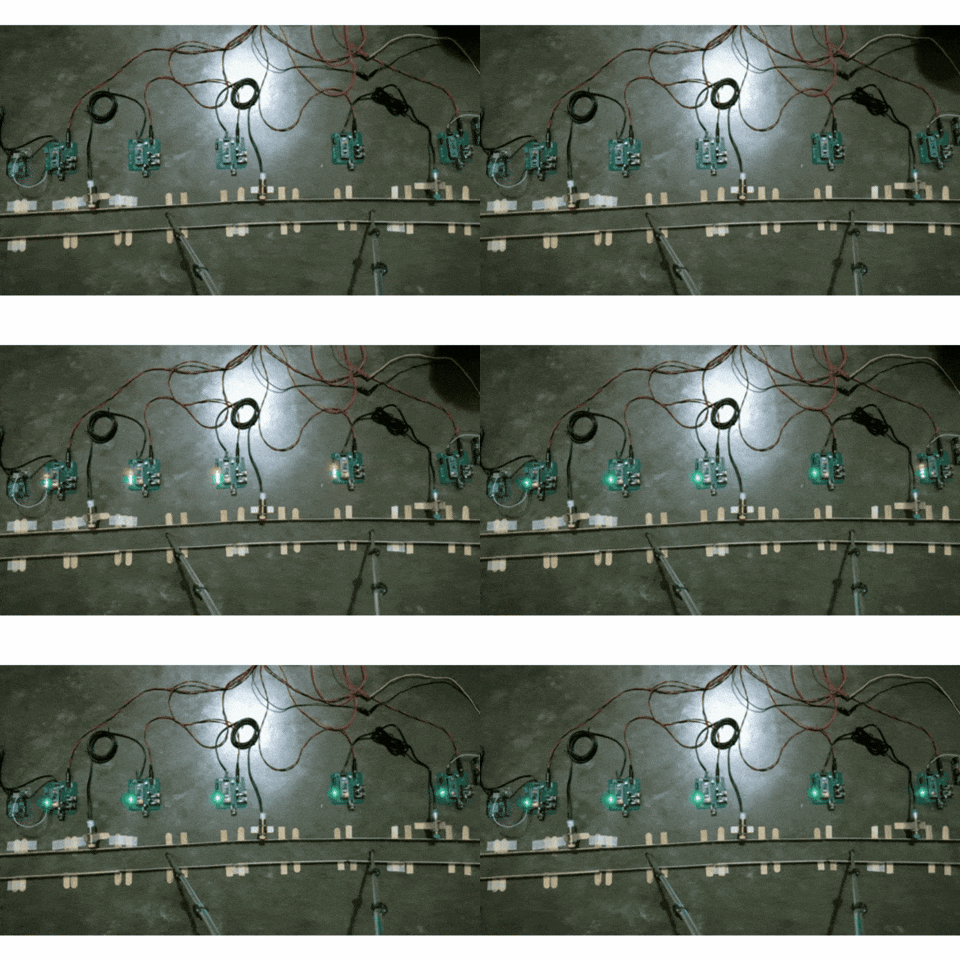
When the signal nodes are first powered up, all the signal LEDs turn ON meaning the nodes are uninitialised. Once they acquire the signal data of other signal nodes as per requirements, the GREEN LED turns ON. The process takes less than a second as you can see in the GIF below.
NOTE:
During initialisation, the tracks must be empty.
Also, the GIF has a low frame rate so it appears that the initialisation process takes longer than a second.
LOCOMOTIVE UNIT
After powering the locomotive node, press the TRAIN_DIR switch and check if the led toggles between D4 and D2.
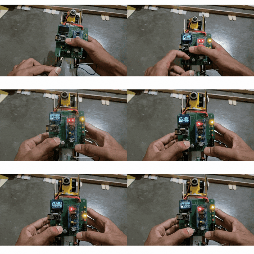
The signal units count the axles of the locomotive using the inductive proximity sensors, but the toy locomotive that I am using for demonstration is made of plastic.
So, I have taped some metal coins to the side to simulate the metal wheel of a real locomotive.

WEB UI
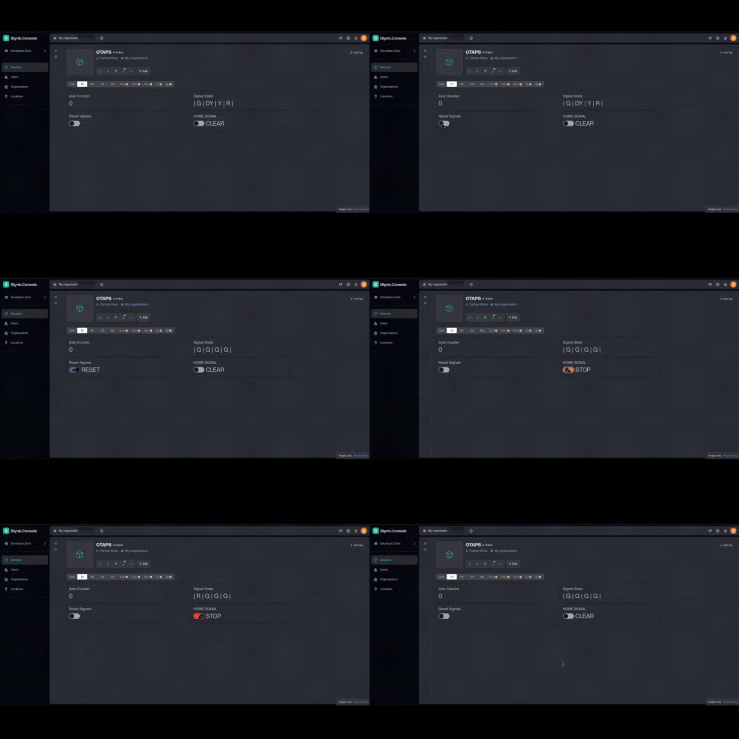
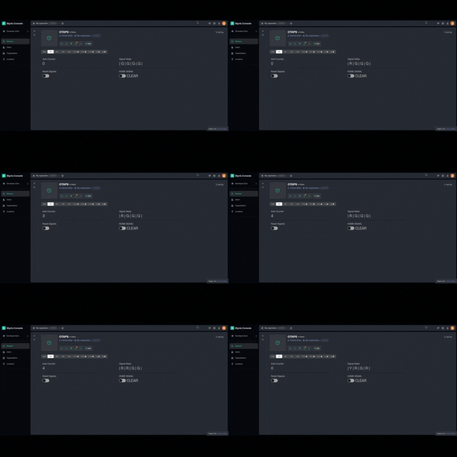
This section shows WEB UI for the station master in action. The Arduino UNO R4 WiFi is connected to the signal node number 1. The gif below shows the axle counter and signal state value changing as the locomotive passes from node 1 to node 5.
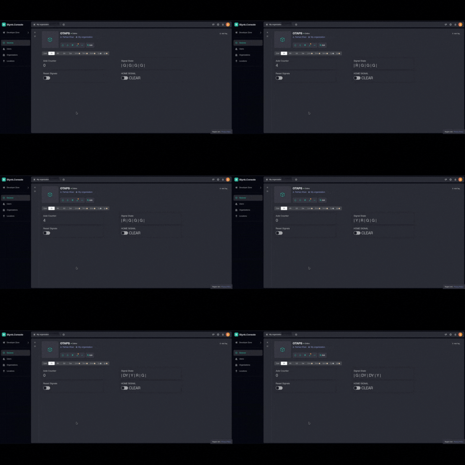
Once the locomotive reaches node 5, the value of the signal units are G, G, DY, Y. The signal can be reset by pressing the Reset Signals switch, the home signal can be toggled between RED and GREEN by HOME SIGNAL switch.
FREIGHT LOCOMOTIVE TRAIN ACCIDENT AT PUNJAB [2]

On 2nd of June 2024, at 3:15am, UP GVGN, a freight train, hit another freight train from behind which was stationary at the Sirhind Junction in Punjab[2]. Investigation revealed that both the loco pilot and the assistant loco pilot of the UP GVGN had dozed off, overshooting a RED signal.
By the time, the loco pilots saw the stationary train, it was too late. The WAG 12 locomotive of the UP GVGN rammed into the stationary freight locomotive leaving the loco pilot and the assistant loco pilot severely injured. A very similar pattern was seen for the 13174 Kanchanjanga Train accident[3] which occured on 17th of June 2024 in West Bengal.

I have setup a similar scenario here, consider the locomotive at B as the stationary freight locomotive at Sirhind Junction, and the other at station A as the UP GVGN locomotive.

The signal state of the signals are:
Signal 1: GREEN
Signal 2: GREEN
Signal 3: DOUBLE YELLOW
Signal 4: YELLOW
Signal 5: RED
As you can see in the GIF below, as the locomotive starts from signal node 1.The locomotive crosses signal 1 with full speed. As it crosses signal 2, it sees that the signal ahead is Double Yellow and Yellow, so it reduces the speed of the locomotive and crosses signal 3.Just as it crosses signal 4, it sees that the signal ahead is RED and it automatically applies the brakes and brings the locomotive to a halt. Thus, preventing a collision.
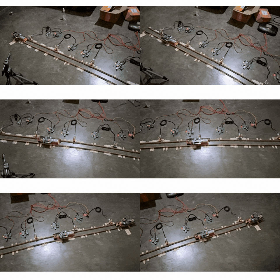
As you can see in the locomotive UI, state of locomotive is STOP, and that of the line is BLK.

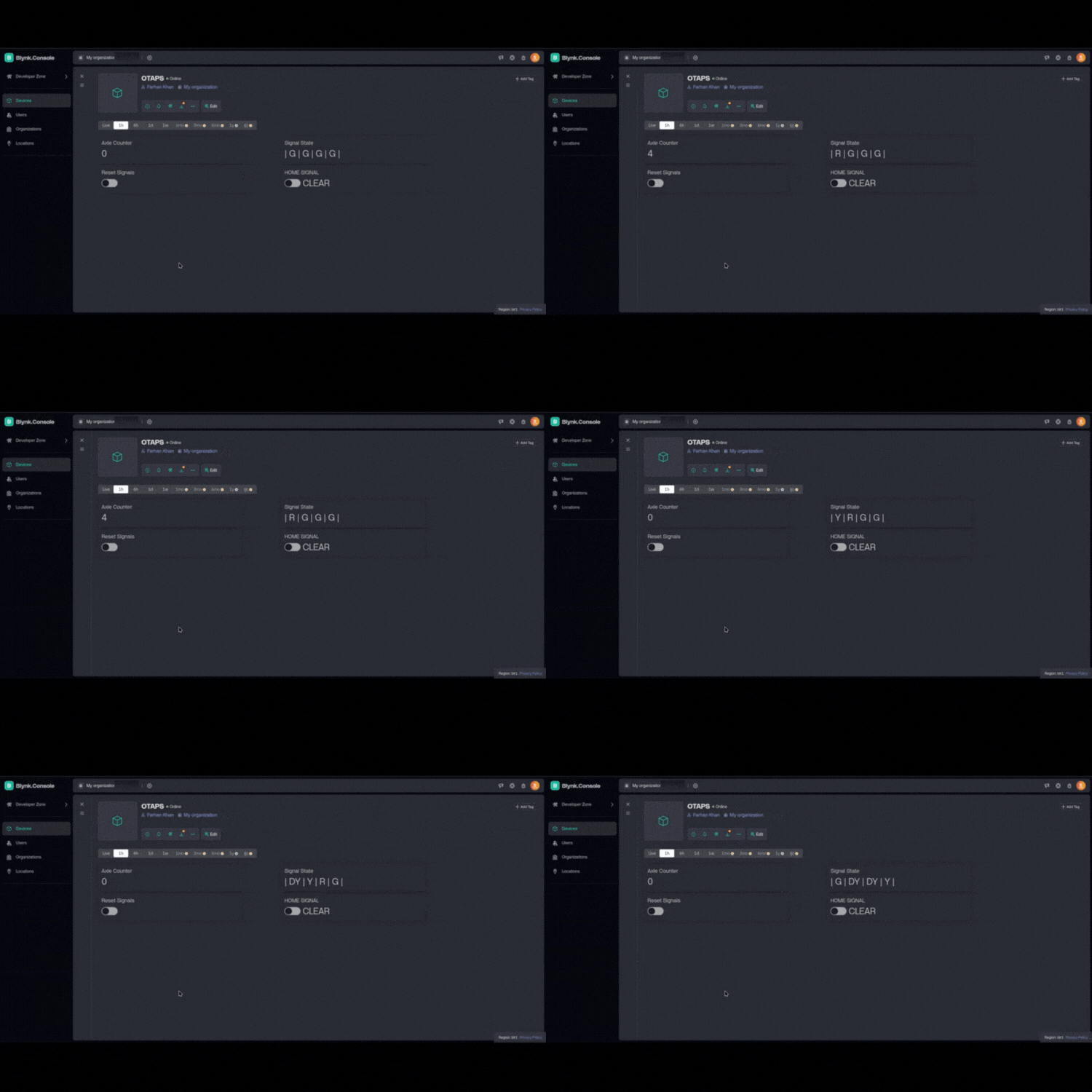
The gif below shows the web UI as the train moves from A to B.
2 TRAINS MOVING TOWARDS EACH OTHER
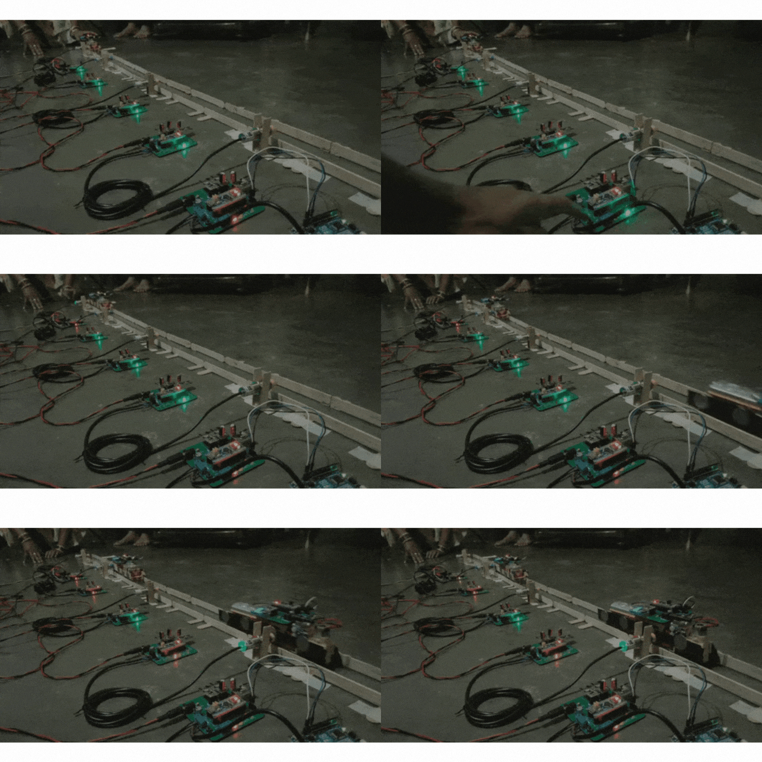
I have setup another scenario in which two trains are moving towards each other on the same track. One locomotive from A would be moving towards be B, and another from B moving towards A.

As you can see in the GIF below, both the locomotive stop before a distance of 2 signals in this case.
WEB UI STATE
LOCOMOTIVE A STATE

LOCOMOTIVE B STATE

To view the code and schematics of the project, please click on the GitHub icon below.
REFERENCES/EXTERNAL LINKS
[1] KAVACH/TCAS Cost
[2] DFCC SIRHIND TRAIN ACCIDENT / SIRHIND TRAIN ACCIDENT FINDING


