

In our previous two tutorials we discussed How to Get Started with PIC using MPLABX and XC8 compiler, we have also made our First LED Blinking Program with PIC and verified it by simulation. Now it's time for us to get our hands on to the hardware. In this tutorial we will build a small circuit on a Perf Board for Blinking the LED using PIC. We will dump the program to our PIC microcontroller and verify the LED Blinking. To Program the PIC MCU we will be using MPLAB IPE.
Materials Required:
As discussed in our previous tutorial we will need the following materials:
- PicKit 3
- PIC16F877A IC
- 40 - Pin IC holder
- Perf board
- 20 MHz Crystal OSC
- Female and Male Bergstick pins
- 33pf Capacitor - 2Nos, 100uf and 10uf cap.
- 680 ohm, 10K and 560ohm Resistor
- LED of any color
- 1Soldering kit
- IC 7805
- 12V adapter
What happens when we "Burn" a Microcontroller!!
It is a usual practise to upload the code into a MCU and get it working inside the MCU.
But what really happens inside the MCU how does few lines of C-Program get into a silicon chip and gets executed?
In, order to understand this lets have a look at our program
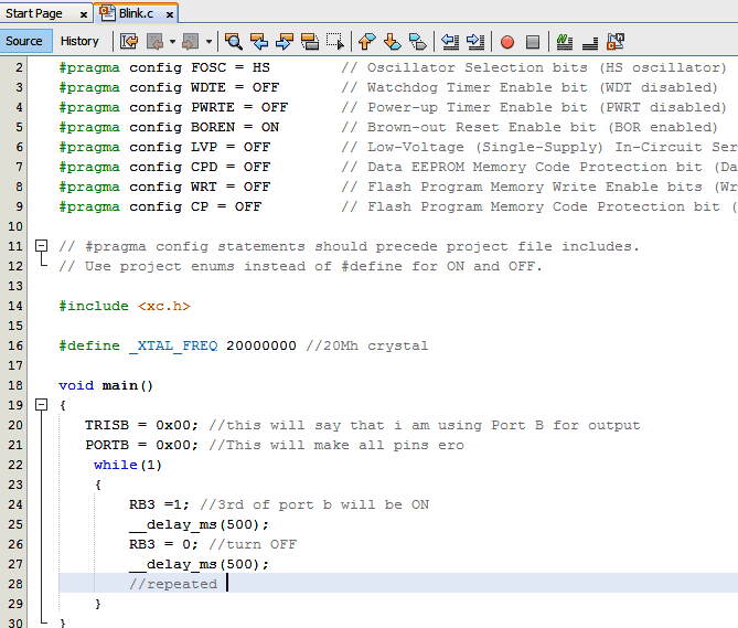
As we can see this code is written in C-Language and it will make no sense to our MCU. This is where the part of our compiler comes in; a Compiler is one which converts this code into a Machine readable form. This machine readable form is called the HEX code, every project that we create will have a HEX code which will be in the following directory
**Your location**\Blink\Blink.X\dist\default\production\Blink.X.production.hex
If you are so interested to know how this HEX code looks like, just open it using the notepad. For our Blink program, the HEX code will look like the following:
:060000000A128A11FC2F18
:100FAA008316031386018312031386018312031324
:100FBA0086150D30F200AF30F100C130F000F00BB1
:100FCA00E42FF10BE42FF20BE42F0000831203133A
:100FDA0086110D30F200AF30F100C130F000F00B95
:100FEA00F42FF10BF42FF20BF42F0000DB2F830107
:060FFA000A128A11D52F36
:02400E007A3FF7
:00000001FF
There are ways on how to read this and how to understand and reverse it back into Assembly language, but it is completely out of scope of this tutorial. So, to simply put it into a nutshell; the HEX is the final software outcome of our coding and this is what will be sent to out by MPLAB IPE for burning the MCU.
Flash memory:
The HEX code is stored into the MCU in a place called Flash memory. The flash memory is the place where our program will be stored inside the MCU and executed from there. Once we compile the program in our MPLABX, we would have got the following information about the type of memory on the Output console
Since we have just compiled a small LED blinking program, the memory summary shows that we have just consumed 0.5% of the available program space and 1.4% of Data space.
Memory of the PIC16F877 microcontroller is basically divided into 3 types:
Program Memory: This memory contains the program (which we had written), after we've burned it. As a reminder, Program Counter executes commands stored in the program memory, one after the other. Since we have written a very small program, we have consumed only 0.5% of the total space. This is a non-Volatile memory, means the stored data won’t be lost after the power off.
Data Memory: This is RAM memory type, which contains a special registers like SFR (Special Function Register) that includes Watchdog timer, Brown out Reset etc. and GPR (General Purpose Register) that includes TRIS and PORT etc. The variables that are stored in the Data Memory during the program are deleted after we turn off the MCU. Any variable declared in the program will be inside the Data memory. This is also a volatile memory.
Data EEPROM (Electrically Erasable Programmable Read-Only Memory): A memory that allows storing the variables as a result of burning the written program. For example if we assign a variable "a" to save a value of 5 in it and store it in the EEPROM this data will not be lost even if the Power is turned OFF. This is a non-Volatile memory.
Program Memory and EEPROM are non-volatile memories, and called as Flash Memory or EEPROM.
ICSP (In Circuit Serial Programming):
We will be programming our PIC16F877A using the ICSP option that is available in our MCU.
Now, What is ICSP?
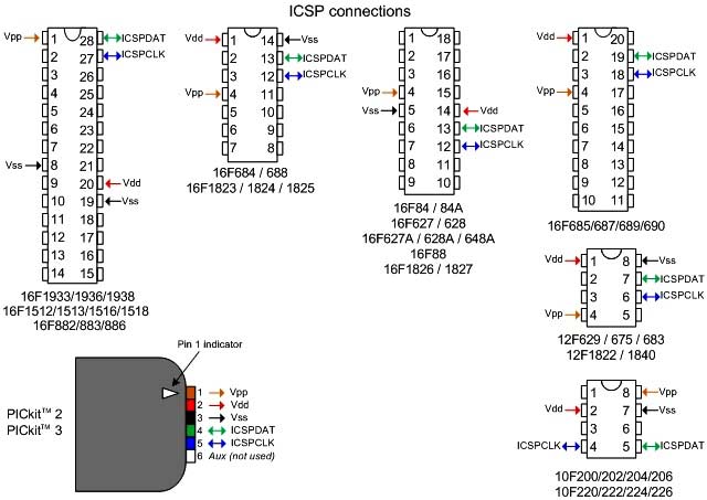
ICSP is a simple way which helps us to program an MCU even after it is placed inside our Project board. There is no need to have a separate programmer board to program the MCU, all we need is 6 connections from the PicKit3 programmer to our board as follows:
1 | VPP (or MCLRn) | To enter programming mode. |
2 | Vcc | Power Pin 11 or 32 |
3 | GND | Ground PIN 12 or 31 |
4 | PGD - Data | RB7. PIN40 |
5 | PGC - Clock | RB6. PIN 39 |
6 | PGM - LVP enable | RB3/RB4. Not mandatory |
ICSP is suitable for all PIC packages; all we need is to pull out these five pins (6th pin PGM is optional) from the MCU to Pickit3 as shown in the picture below.
Circuit and Hardware:
Now, we have our HEX code ready and we also know how to connect our PicKit 3 to our PIC MCU using ICSP. So, let's go ahead and solder the circuit with help of the below schematics:

In the above circuit I have used a 7805 to regulate the output 5V to my PIC MCU. This regulator will be powered by a 12V wall mart adapter. The RED Led is used to indicate if the PIC is powered. The connector J1 is used for ICSP programming. The pins are connected as discussed in the above table.
The first pin MCLR must be held high with help of a 10k by default. This will prevent the MCU from resetting. In order to reset the MCU the pin MCLR must be held to ground which can be done with the help of switch SW1.
The LED is connected to the pin RB3 through a resistor of value 560 ohms (See LED resistor calculator). If everything is proper once our program is uploaded this LED should blink based on the program. Whole circuit is built on Perfboard by soldering all the components on it as you can see in the image at the top.
Burning the Code using MPLAB IPE:
To burn the code, follow below steps:
- Launch the MPLAB IPE.
- Connect one end of your PicKit 3 to your PC and other end to your ICSP pins on perf board.
- Connect to your PIC device by clicking on the connect button.
- Browse for the Blink HEX file and click on Program.
If, everything goes as planned you should get the success message on the screen. Check the Code and Video below for Full demonstration and use the comment section if you have any doubt.
Thank you!!!
Let’s meet in the Next tutorial where we will play with more LED's and a switch.
Complete Project Code
// 'C' source line config statements
// CONFIG
#pragma config FOSC = HS        // Oscillator Selection bits (HS oscillator)
#pragma config WDTE = OFF       // Watchdog Timer Enable bit (WDT disabled)
#pragma config PWRTE = OFF      // Power-up Timer Enable bit (PWRT disabled)
#pragma config BOREN = ON       // Brown-out Reset Enable bit (BOR enabled)
#pragma config LVP = OFF        // Low-Voltage (Single-Supply) In-Circuit Serial Programming Enable bit (RB3 is digital I/O, HV on MCLR must be used for programming)
#pragma config CPD = OFF        // Data EEPROM Memory Code Protection bit (Data EEPROM code protection off)
#pragma config WRT = OFF        // Flash Program Memory Write Enable bits (Write protection off; all program memory may be written to by EECON control)
#pragma config CP = OFF         // Flash Program Memory Code Protection bit (Code protection off)
// #pragma config statements should precede project file includes.
// Use project enums instead of #define for ON and OFF.
#include <xc.h>
    #define _XTAL_FREQ 20000000 //Specify the XTAL crystall FREQ
void main() //The main function
{
TRISB=0X00; //Instruct the MCU that the PORTB pins are used as Output.
PORTB=0X00; //Make all output of RB3 LOW
while(1) //Get into the Infinie While loop
{
    RB3=1; //LED ON
    __delay_ms(100); //Wait
    RB3=0; //LED OFF
    __delay_ms(100); //Wait

    //Repeat.
}
}
Comments
Thanks Murali,
Currently there are about 15 tutorials for the PIC MCU. Learn all them to enhance advanced skills.
It was great and very much helpful for beginners, but can you elaborate on the selection of hardware like why 1nF capacitor is only used?
Hi
thank you very much for such a good tutorial .I would like to the use pickit3 and oscillator.
Hi,
I have followed your tutorials on pic controller and am trying to use them in my project. I have tried to test my controller with the LED blinking program. I have used a dumping kit in our lab to dump the program, but not picKit 3. And i have built the circuit . But its not working, the LED is not blinking. What could be the possible reason for its failure? There was no problem while dumping the code!
thank you.
Double check if the program is being uploaded successfully
Are you using the same program? If not check if your configuration register is set correctly
Hi,
Your tutorials are very informative and helpful in my project. But am using a dumping kit in our lab. Though the code is being successfully dumped, the circuit is not producing the output even for the simple LED blinking program.What could be the possible reason for it? Do we have to use only pickit3 for dumping?
Thank you
No you can use any kit to dumb the program. Are you sure the program is uploaded successfuy?
Did you use the same program?
Try using a multimeter on the digital pin to check its status
thank you for this insightful tutorial. I am working on 7X35 display (with five 7X5 display modules cascaded together, shift register,74HC595, ULN2803 buffer ic)... Though my code is working partially with a scrolling message but instead of the characters to scroll from one display module to another, characters scroll on each individual display module... Pls I dnt know if you can help me if I send d code (C Lang) and circuit.. Thanks
hi,
could you clarify about resistor value R1,R2,R3 are there
respectively 560 ;10k;560
or
respectively 560 ;1k;10k
thanks a lot
I have used the same program. But the led is glows and never Blink.
Did your simulation work? Have you connected it to the same pin>?
The circuit diagram and the table for the icsp connections are contradicting each other. In the table pin 4 is connected to pin 40 while pin 5 is connected to pin 39 but in the circuit diagram pin 4 is connected to pin 39 while pin 5 is connected to pin 40. Can you please clarify which one is correct.
Hi Guys,
Firstly thanks for creating such a great platform it is a savior for many
Coming to my question
you are using c language for programming and how does the delay is defined. as far as I know, there is no direct command in Assembly language that helps us to define the delay and get a desired delay .
Can you please explain how the delay routines work in blinking the LED
Kind Regards
Hi,
With regard to the connection of pins 4 and 5 of the PICkit 3 - the circuit diagram is incorrect and the table is correct.
That is to say, Pin 4 of the PICkit goes to Pin 40 of the PIC16F877A and respectively, Pin 5 goes to Pin 39.
Check the 40 pin PDIP diagram on page 3 of the PIC16F87xA Data Sheet and compare it with Fig 2-4 on page 20 of the PICkit™ 3 User’s Guide.
Regards,
MGC

Excellent tutorial, thank you so much , made my learning easy . Expecting more advanced lessons from you .