
Hey everyone, in this tutorial we are going to interface a Liquid Crystal Display (LCD) module with the Raspberry Pi Pico using Micropython. By the end of this tutorial, you will be able to display strings, characters on the LCD using Micropython. Before beginning this tutorial, I'm presuming that you've already followed our tutorial series on Raspberry Pi Pico. Previously we have worked with an OLED display and we have seen the I2C and ADC on the Raspberry Pi Pico. Now, let’s see how to interface an LCD display module with the pico board.
16x2 Liquid Crystal Display Module
The 16x2 LCD gets its name from the fact that it contains 16 columns and 2 rows. As a result, it will contain a total of (16x2=32) 32 characters, with each character consisting of 5x8 Pixel Dots. The image below depicts a single character with all of its pixels.
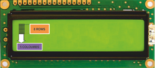
Each character has a size of (5x8=40) 40 pixels, giving us a total of (32x40) 1280 pixels for 32 characters. Additionally, the LCD instructions should be told where the pixels are located. As a result, controlling everything using a microcontroller will be challenging. So, an interface IC, such as the HD44780, is used on the backside of the LCD Module. More information is available in the HD44780 Datasheet.
This IC's job is to take commands and data from the MCU and process them so that relevant information may be shown on the LCD screen. Without a backlight, the LCD's working voltage ranges from 4.7 to 5.3 volts and its current usage is 1mA. It is capable of working in both 8-bit and 4-bit modes. These LCDs come with a green or blue backlight and may also show any characters created by the user.
Pinout and Pin Description of the 16x2 LCD Module
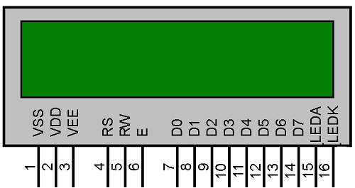
The LCD display will have 16 Pins. The Pinout and Pin Description of the 16x2 LCD Module is mentioned in the table below. You can refer to this article on 16x2 LCD Display Module on our website for more details about the LCD pinouts.
Sr. No | Pin No. | Pin Name | Pin Type | Pin Description | Pin Connection |
1 | Pin 1 | Ground | Source Pin | This is a ground pin of LCD | Connected to the ground of the MCU/ Power source |
2 | Pin 2 | VCC | Source Pin | This is the supply voltage pin of LCD | Connected to the supply pin of Power source |
3 | Pin 3 | V0/VEE | Control Pin | Adjusts the contrast of the LCD. | Connected to a variable POT that can source 0-5V |
4 | Pin 4 | Register Select | Control Pin | Toggles between Command/Data Register | Connected to a MCU pin and gets either 0 or 1. 0 -> Command Mode 1-> Data Mode |
5 | Pin 5 | Read/Write | Control Pin | Toggles the LCD between Read/Write Operation | Connected to a MCU pin and gets either 0 or 1. 0 -> Write Operation 1-> Read Operation |
6 | Pin 6 | Enable | Control Pin | Must be held high to perform Read/Write Operation | Connected to MCU and always held high. |
7 | Pin 7-14 | Data Bits (0-7) | Data/Command Pin | Pins used to send Command or data to the LCD. | In 4-Wire Mode Only 4 pins (0-3) is connected to MCU In 8-Wire Mode All 8 pins(0-7) are connected to MCU |
8 | Pin 15 | LED Positive | LED Pin | Normal LED like operation to illuminate the LCD | Connected to +5V |
9 | Pin 16 | LED Negative | LED Pin | Normal LED like operation to illuminate the LCD connected with GND. | Connected to ground |
Circuit Diagram of LCD Interfacing with the Pico Board
The following circuit diagram is representing the connection of the LCD to the Raspberry Pi Pico. I have used a potentiometer to control the brightness of the LCD display. The 4-bit data pins (i.e. D4 to D7) are connected to the GPIOs 18,19,20,21 respectively. The Rs pin of the LCD is connected to the GPIO 16 and the E pin is connected to the GPIO 17. The output of the potentiometer is connected to the V0 pin of the LCD and the VBUS pin is connected to the input terminal of the potentiometer. This VBUS pin of the pico is used to power the LCD via VDD pin of the LCD. Pin number 15 of the LCD is connected to the VDD pin of the LCD to provide the power supply of 5V and Pin number 16 of the LCD is connected to the Ground pin followed by the RW pin of the LCD.

Programming the LCD with Raspberry Pi Pico Using MicroPython
To program the LCD with Raspberry Pi Pico using Micropython, you need to download the respective library and code files from our GITHUB repository of the Raspberry Pi Pico Tutorial Series. When you open the “codes”, you will get two python files named “lcd_pico.py” and “main.py”. The “lcd_pico” can be used as a library to program the LCD display with Raspberry Pi Pico using Micropython. In the “main.py” file I have used some functions from the “lcd_pico.py” file to display some strings on the LCD. Let’s discuss both python files one by one.
The Lcd_pico.py file
In the “lcd_pico.py” file, we have imported two libraries “machine.py” and the “utime.py”. The machine library contains the built-in functions to define the Pins, GPIOs, etc. The “utime” library is used to provide the delay in the code. Then I have defined the GPIO pins for the 4-bit data pins of the LCD and the RS and E pin of the LCD. The “machine.Pin(16,machine.Pin.OUT)” is used to set the GPIO21 as OUTPUT and assign this in the “rs” variable. Similarly, the GPIOs 17 to 21 are set as OUTPUT pins and assigned to the “e”, “d4”, “d5”, “d6”, and “d7” variables respectively.
import machine
import utime
rs= machine.Pin(16,machine.Pin.OUT)
e = machine.Pin(17,machine.Pin.OUT)
d4 = machine.Pin(18,machine.Pin.OUT)
d5 = machine.Pin(19,machine.Pin.OUT)
d6 = machine.Pin(20,machine.Pin.OUT)
d7 = machine.Pin(21,machine.Pin.OUT)
The “setCursor(line,pos)” function below is used to set the position of the cursor. We need to pass two parameters “line” and “pos”. In my case, I am using the 16x2 LCD which has 2 lines to set the cursor. And the “pos” is used to set the position where we want to print the data.
def setCursor(line, pos):
    b = 0
    if line==1:
        b=0
    elif line==2:
        b=40
    returnHome()
    for i in range(0, b+pos):
        moveCursorRight()
The clearScreen() function is used to clear the display screen and the setupLCD() function is used to initialized the LCD. We need to use the setupLCD() function at the starting of our main code. The displayString() is used to display any String data. This function takes three parameters that are “row”, “col” and the “input_string”. The “row” and “col” are used to set the cursor position and the “input_string” is used to pass the string that needs to be print on the LCD.
def clearScreen():
    rs.value(0)
    send2LCD8(0b00000001)#clear screen
    longDelay(2)#clear screen needs a long delay
    rs.value(1)
def setupLCD():
    rs.value(0)
    send2LCD4(0b0011)
    send2LCD4(0b0011)
    send2LCD4(0b0011)
    send2LCD4(0b0010)
    send2LCD8(0b00101000)
    send2LCD8(0b00001100)#lcd on, blink off, cursor off.
    send2LCD8(0b00000110)#increment cursor, no display shift
    send2LCD8(0b00000001)#clear screen
    longDelay(2)#clear screen needs a long delay
    rs.value(1)
def displayString(row, col, input_string):
    setCursor(row,col)
    for x in input_string:
        send2LCD8(ord(x))
        longDelay(10)
The main.py file
In the main.py file, I have imported the “lcd_pico” library and then I have called the “setupLCD()” function. Then I used the “displayString()” function to print the following strings. In this function, I have passed the “row” and “col” to set the cursor position and then I have passed the strings to be displayed on the LCD. The longDelay() function is used to provide the delay in microseconds.
from lcd_pico import *
setupLCD()
displayString(1,0,"WELCOME")
displayString(2,0,"TO")
longDelay(4000)
displayString(1,0,"CIRCUIT")
displayString(2,0,"DIGEST")
longDelay(4000)
In the while loop below I have used the displayString() to display the “CIRCUIT DIGEST” with 1.5 seconds of interval. The clearScreen() is used to clear the display screen in every 1.5 Seconds.
while(True):
displayString(1,0,"CIRCUIT")
displayString(2,0,"DIGEST")
longDelay(1000)
clearScreen()
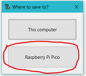
longDelay(500)Now, in the Thonny IDE, open the “main.py” and “lcd_pico.py” files. To begin, save the “lcd_pico.py” file on the Pico board by pressing the “ctrl+shift+s” keys on your keyboard. Before saving the files, make sure your Pico board is connected to your laptop. When you save the code, a popup window will appear, as shown in the image below. You must first select the Raspberry Pi Pico, then name the file “lcd_pico.py” and save it. Then repeat the process for the “main.py” file. This procedure enables you to run the program when the Pico is turned on.
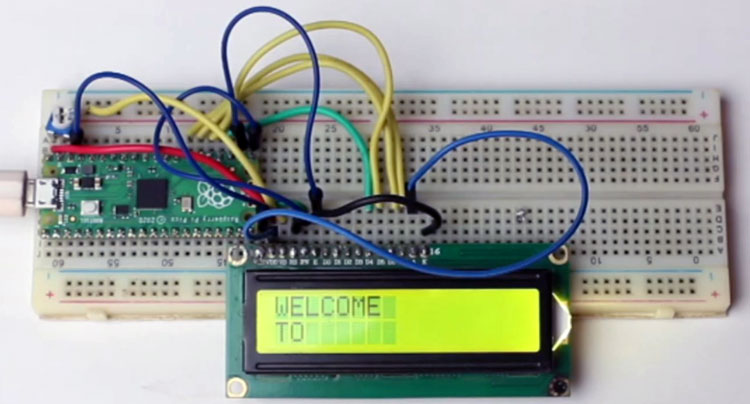
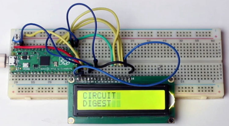
When you upload and run the code on the pico board, you will see the output similar to the images below. The first image is showing the “WELCOME” string in the first row of the LCD and “TO” string in the second row of the LCD. Then after 4 seconds of delay, it is displaying the “CIRCUIT” string in the 1st line of the LCD and “DIGEST” string in the 2nd line of the LCD.
I have explained the code and the connection setup of the hardware in the video below.
Complete Project Code
def pulseE():
    e.value(1)
    utime.sleep_us(40)
    e.value(0)
    utime.sleep_us(40)
def longDelay(t):
    utime.sleep_ms(t)
def shortDelay(t):
    utime.sleep_us(t)
def send2LCD4(BinNum):
    d4.value((BinNum & 0b00000001) >>0)
    d5.value((BinNum & 0b00000010) >>1)
    d6.value((BinNum & 0b00000100) >>2)
    d7.value((BinNum & 0b00001000) >>3)
    pulseE()
def send2LCD8(BinNum):
    d4.value((BinNum & 0b00010000) >>4)
    d5.value((BinNum & 0b00100000) >>5)
    d6.value((BinNum & 0b01000000) >>6)
    d7.value((BinNum & 0b10000000) >>7)
    pulseE()
    d4.value((BinNum & 0b00000001) >> 0)
    d5.value((BinNum & 0b00000010) >> 1)
    d6.value((BinNum & 0b00000100) >> 2)
    d7.value((BinNum & 0b00001000) >> 3)
    pulseE()
def setCursor(line, pos):
    b = 0
    if line==1:
        b=0
    elif line==2:
        b=40
    returnHome()
    for i in range(0, b+pos):
        moveCursorRight()
def returnHome():
    rs.value(0)
    send2LCD8(0b00000010)
    rs.value(1)
    longDelay(2)
def moveCursorRight():
    rs.value(0)
    send2LCD8(0b00010100)
    rs.value(1)
def setupLCD():
    rs= machine.Pin(16,machine.Pin.OUT)
    e = machine.Pin(17,machine.Pin.OUT)
    d4 = machine.Pin(18,machine.Pin.OUT)
    d5 = machine.Pin(19,machine.Pin.OUT)
    d6 = machine.Pin(20,machine.Pin.OUT)
    d7 = machine.Pin(21,machine.Pin.OUT)
    rs.value(0)
    send2LCD4(0b0011)
    send2LCD4(0b0011)
    send2LCD4(0b0011)
    send2LCD4(0b0010)
    send2LCD8(0b00101000)
    send2LCD8(0b00001100)#lcd on, blink off, cursor off.
    send2LCD8(0b00000110)#increment cursor, no display shift
    send2LCD8(0b00000001)#clear screen
    longDelay(2)#clear screen needs a long delay
    rs.value(1)
def displayString(row, col, input_string):
    setCursor(row,col)
    for x in input_string:
        send2LCD8(ord(x))
        utime.sleep_ms(100)
..............................................................................................................................
from lcd_pico import *
setupLCD()
displayString(1,0,"WELCOME")
displayString(2,0,"TO")
longDelay(4000)
displayString(1,0,"CIRCUIT")
displayString(2,0,"DIGEST")
longDelay(4000)
while(True):
    displayString(1,0,"CIRCUIT")
    displayString(2,0,"DIGEST")
    longDelay(1000)
    clearScreen()
    longDelay(500)

what if you have a IC2 LCD Display that only needs 4 connections how would you go about using that