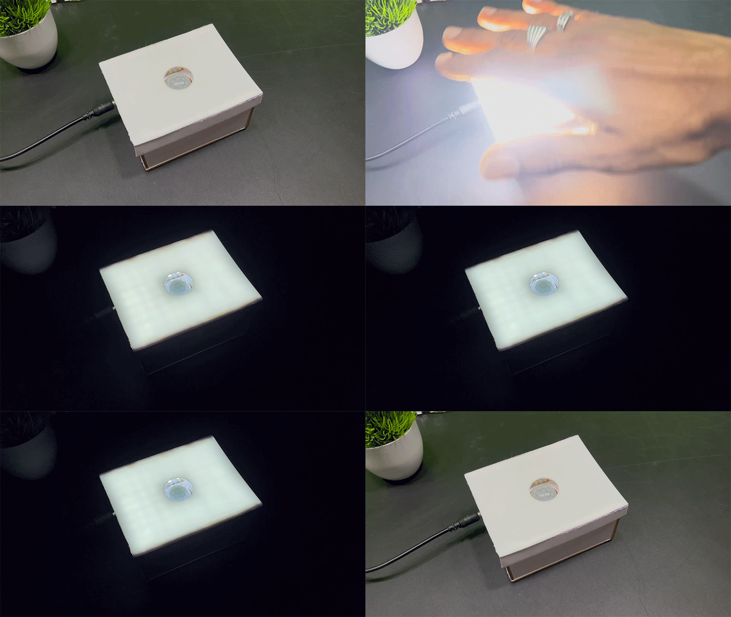
In today's world of smart technology, creating simple yet effective DIY projects without the use of microcontrollers or complex integrated circuits is both a challenge and a rewarding experience. One such project is the creation of a motion sensor light using a Passive Infrared (PIR) sensor, a relay, and a bulb. In this project, we'll learn how to make a motion sensor light without the need for a microcontroller. A motion sensor light turns on when it senses movement nearby. It's handy for lighting up an area when someone walks by, helping them see better. Previously, we have also built a similar project called PIR Motion Sensor Light Bulb, but this time we will use LED lights so that it look more cool and is very practical to use. So without any further ado lets learn how to make a motion sensor light, using a motion sensor 
Overview of PIR Sensor

Living objects with a body temperature above 0°C emit heat as infrared radiation, also known as thermal radiation, which is invisible to the human eye. PIR sensors, designed for this purpose, can detect these signals, allowing for the identification of infrared radiation emitted by living organisms.

The term "passive" in PIR sensor (Passive Infrared Sensor) signifies that it doesn't emit energy for detection. PIR sensors do not measure heat directly but rather detect infrared radiation emitted or reflected by objects. These sensors are compact, affordable, low-power, and user-friendly, commonly used in homes, medical settings, factories, and various other applications.
If you are interested in building more project using PIR sensor you can check out the tutorial on how to use PIR sensor with Arduino. For this homemade motion sensor light project though we wanted to keep things easy so we have not used Arduino or any other microcontroller. The block diagram for DIY PIR Motion sensor light is shown below.

Required Components for PIR Motion Sensor Light
PIR Motion sensor
Transistor BC547(NPN)
Relay module
12V Led strip
Resistor 10k
12V DC socket
Connecting wires
12V DC Adaptor / Battery
PIR Motion Sensor Light Circuit
The circuit involves a PIR sensor as the motion detector, a relay to control the power to the bulb, and a transistor to drive the relay. The PIR motion sensor light wiring diagram is shown below.
The basic idea is to amplify the output signal from the PIR sensor to control the relay, which, in turn, switches the bulb on or off. The required components to build this motion detector circuit mainly include a 5V relay, PIR sensor, BC547 Transistor, 10KΩ resistor,12V led strip, and 12V DC socket. Give the connections as per the circuit shown below.

Design and Assembly of PIR Motion Sensor Light
I created the custom box from the MDF board specifically for this project, and you can see screenshots of the CAD design with the dimension’s I made using Onshape, as well as the actual design I built, in the images below. If you're interested in recreating this project or incorporating my design into your own work, I've included the CAD .dxf files, which you can download here.

In this tutorial video, I have covered the Assembly of the hardware with required components and control relay with PIR sensor for LED. the below image shows the final product after wiring, soldering and assembly.

Working of PIR Motion Sensor Light
This setup uses a few basic and easy-to-find electronic parts. The main player here is the Passive Infrared (PIR) sensor, which has three terminals. When this sensor detects human motion, it generates a logical output. The output pin of the PIR sensor is crucial in this setup it connects to the base terminal of the BC547 switching transistor.

The relay, a key component for controlling the electrical circuit, is connected to the collector terminal of the transistor. The other end of the relay coil is linked to the positive supply. The LED is connected to the Normally Open (N/O) terminal of the relay. When the relay is activated, the common pin connects with the N/O pin, completing the circuit and causing the LED to illuminate. The output of the sensor is automatic LOW after a time duration set by the user. So the light which is connected is automatically switched off after some time. PIR sensor has 2 presets, one is adjustment of sensitivity of its and second is the adjustment of time delay which remain high at output for a duration.

This motion detector circuit is versatile and can be installed in various locations, such as the front gate or staircase. Upon detecting movement, the PIR sensor triggers the relay, initiating the glow of the bulb. This simplicity makes it suitable for applications like security systems, standalone alarms, or basic light automation setups. The circuit provides a practical solution for enhancing visibility in response to human motion.
Applications and Uses
PIR sensor lamps are commonly employed for energy conservation by detecting human and animal motion, commonly employed in security systems, street lights, and outdoor spaces like lift lobbies, common staircases, parking areas, and gardens. Their applications extend to various settings where motion-sensing lighting is beneficial for energy efficiency and security.


