 using Arduino IDE")
What is OTA Programming?
OTA Programming (Over the Air) is a process which allows devices to upgrade their firmware or software wirelessly without any physical access. It uses wireless technology like Wi-Fi, Bluetooth, GPRS or 4G/3G rather than wired serial communication. OTA is used to reprogram the devices like microcontrollers, cellphones, computers, set-top box etc. OTA updates are generally sent for updating the software, resolving the bugs, adding some features etc. With the increasing use of IoT devices OTA is transferred using frequency bands having low data transmission rate (868 MHz, 900 MHz, 2400 MHz).
Here in this tutorial, we will send OTA update to ESP8266 NodeMCU to blink an LED.
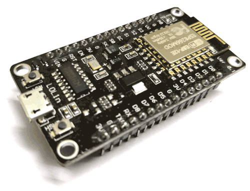
ESP8266 NodeMCU
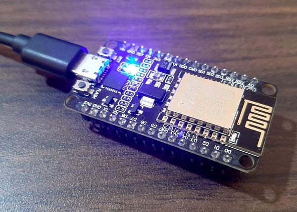
NodeMCU is an open source IoT platform. It includes firmware which runs on the low cost Wi-Fi enabled ESP8266 Wi-Fi SoC from Espressif Systems, and hardware which is based on the ESP-12 module. It has GPIO, SPI, I2C, ADC, PWM AND UART pins. It can be programmed with Arduino IDE. On board NodeMCU has CP2102 IC which provides USB to TTL functionality. To learn more about ESP8266, check other ESP8266 based projects.
Components Required
- NodeMCU ESP8266
- Micro USB Cable
- Arduino IDE
Preparing NodeMCU to receive OTA Update Wirelessly
First connect the NodeMCU ESP8266 with the PC using micro USB cable. Then, to upload the firmware using OTA, we need to upload the sketch serially using micro USB to generate the ESP IP address. This is the necessary step to upload the firmware wirelessly next time. Select the serial port to which cable is attached from Tools -> Port.
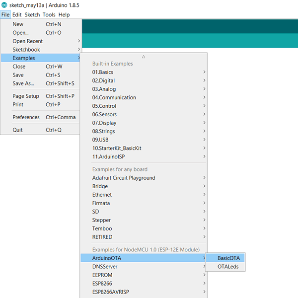
ESP8266 comes with libraries and examples which can be directly accessed from Arduino IDE. Open Arduino IDE and then Open BasicOTA example.
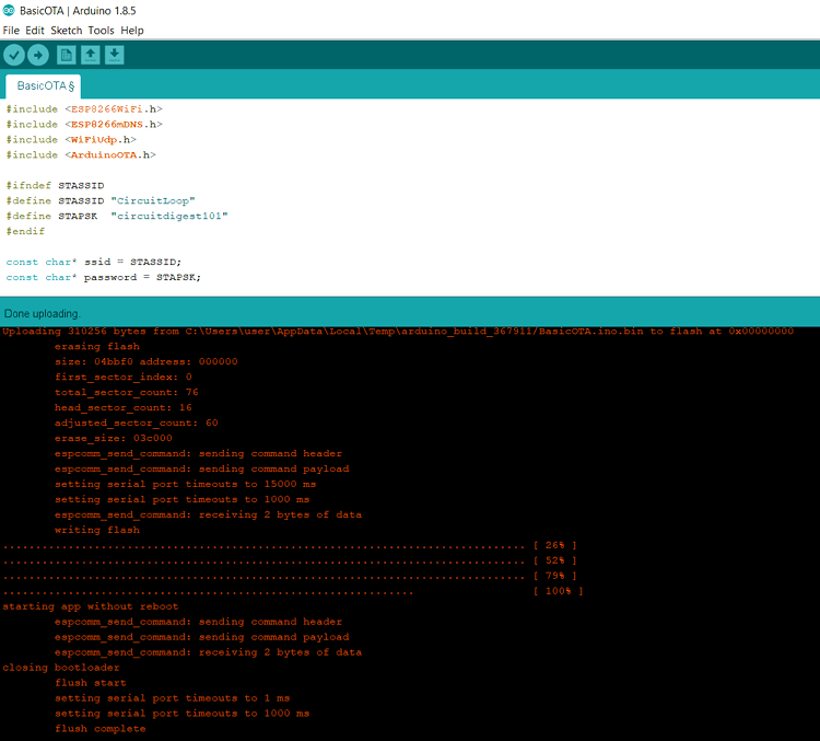
Edit the sketch by replacing “your-ssid” and “your-password” by your Wi-Fi SSID and password and then upload the sketch
Open serial monitor after uploading the program successfully. Set the Baud Rate of 115200 on Serial Monitor and press Reset button on NodeMCU ESP8266. Connecting NodeMCU ESP8266 with Wi-Fi takes some time as it checks the Wi-Fi credentials. If the SSID and password are correct then NodeMCU ESP8266 will get connected to Wi-Fi and IP address of the ESP will display on the serial monitor.

ESP8266 Blinking LED program for OTA Transfer
Complete code for transferring the blinking LED program through OTA is given at the end, here we are explaining some important part of the code.
Importing the required libraries is the first step in writing the code. ESP8266WiFi.h library provides ESP8266 specific Wi-Fi routines needed to connect to a network. Also it provides methods and properties to operate ESP8266 in station mode or soft access point mode. ESP8266mDNS.h allows sketch to respond to multicast DNS queries.
#include <ESP8266WiFi.h>          //provides ESP8266 specific Wi-Fi routines we are calling to connect to network.
#include <ESP8266mDNS.h>
#include <WiFiUdp.h>
#include <ArduinoOTA.h> //OTA libraries
Define variables for SSID and password of the Wi-Fi network to which ESP is to be connected. We have to connect our PC and ESP to the same Wi-Fi network.
#ifndef STASSID
#define STASSID "your-ssid"
#define STAPSK  "your-password"
#endif

const char* ssid = STASSID;
const char* password = STAPSK;
ESP8266 is set as station mode and Wi-Fi connection is initiated by giving credentials. It takes some time for ESP to connect to Wi-Fi module. If SSID and password are correct it gets connected to Wi-Fi and if SSID and password are not correct then it will reboot in every 1 second.
Serial.begin(115200);                //Set Baud Rate to 115200
  Serial.println("Booting");
                                                     // Step to connect ESP with the Wi-Fi
  WiFi.mode(WIFI_STA);          //Set ESP as station mode
  WiFi.begin(ssid, password);      //Wi-Fi Credentials
  while (WiFi.waitForConnectResult() != WL_CONNECTED)        //Connecting  ESP to wi-fi takes some time, so wait till it gets connected
 {
    Serial.println("Connection Failed! Rebooting...");
    delay(1000);
    ESP.restart();
  }
IP address of the ESP is printed on the serial monitor as connecting to the Wi-Fi module. WiFi.localIP() gives the IP address of ESP.
After uploading the code successfully open serial monitor at 115200 Baud Rate. Press the reset button and after few seconds you will be able to see ESP IP address on the Serial Monitor. Now you will be able to upload the firmware wirelessly.
Blinking the LED on ESP8266 through OTA update
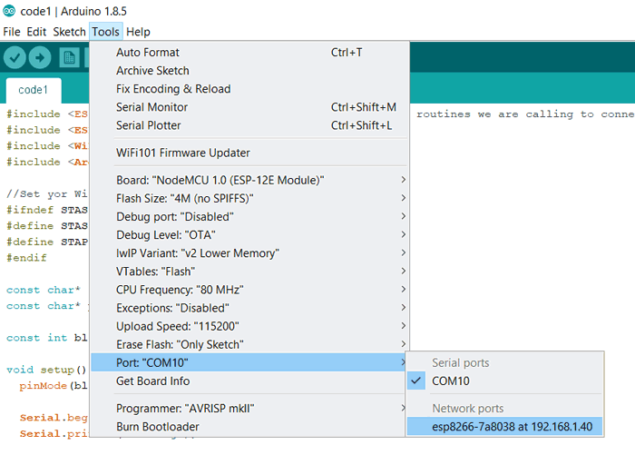
Before uploading the next sketch go to Tools and change PORT to ESP IP address for uploading the firmware wirelessly to the NodeMCU.
Now upload the below given sketch of blinking LED on NodeMCU wirelessly using Arduino IDE and make sure that your PC and ESP are connected to same Wi-Fi network and ESP is powered by some power source.
After uploading the code successfully, LED on NodeMCU ESP8266 will start blinking every 1 second. You can also set host name and password in the sketch for security while uploading firmware on ESP.
Complete Project Code
#include <ESP8266WiFi.h>         //provides ESP8266 specific Wi-Fi routines we are calling to connect to network.

#include <ESP8266mDNS.h>

#include <WiFiUdp.h>

#include <ArduinoOTA.h>  // OTA library
#ifndef STASSID

#define STASSID "your-ssid"

#define STAPSK  "your-password"

#endif
const char* ssid = STASSID;

const char* password = STAPSK;
const int blink_led = D0;  // LED pin on NodeMCU ESP8266
void setup() {

  pinMode(blink_led,OUTPUT);


  Serial.begin(115200);           //Set Baud Rate

  Serial.println("Booting");

                                                   // Step to connect ESP with the Wi-Fi

  WiFi.mode(WIFI_STA);               //Set ESP as station mode

  WiFi.begin(ssid, password);      //Wi-Fi Credentials
  while (WiFi.waitForConnectResult() != WL_CONNECTED)      //Connecting  ESP to wi-fi takes some time, so wait till it gets connected

{

    Serial.println("Connection Failed! Rebooting...");

    delay(1000);

    ESP.restart();

  }
  // Port defaults to 8266

  // ArduinoOTA.setPort(8266);
  // Hostname defaults to esp8266-[ChipID]

  // ArduinoOTA.setHostname("myesp8266");
  // No authentication by default

  // ArduinoOTA.setPassword("admin");
  // Password can be set with it's md5 value as well

  // MD5(admin) = 21232f297a57a5a743894a0e4a801fc3

  // ArduinoOTA.setPasswordHash("21232f297a57a5a743894a0e4a801fc3");
  ArduinoOTA.onStart([]() {

    String type;

    if (ArduinoOTA.getCommand() == U_FLASH) {

      type = "sketch";

    } else { // U_SPIFFS

      type = "filesystem";

    }
    // NOTE: if updating SPIFFS this would be the place to unmount SPIFFS using SPIFFS.end()

    Serial.println("Start updating " + type);

  });

  ArduinoOTA.onEnd([]() {

    Serial.println("\nEnd");

  });

  ArduinoOTA.onProgress([](unsigned int progress, unsigned int total) {

    Serial.printf("Progress: %u%%\r", (progress / (total / 100)));

  });

  ArduinoOTA.onError([](ota_error_t error) {

    Serial.printf("Error[%u]: ", error);

    if (error == OTA_AUTH_ERROR) {

      Serial.println("Auth Failed");

    } else if (error == OTA_BEGIN_ERROR) {

      Serial.println("Begin Failed");

    } else if (error == OTA_CONNECT_ERROR) {

      Serial.println("Connect Failed");

    } else if (error == OTA_RECEIVE_ERROR) {

      Serial.println("Receive Failed");

    } else if (error == OTA_END_ERROR) {

      Serial.println("End Failed");

    }

  });

  ArduinoOTA.begin();          //OTA initialization

  Serial.println("Ready");

  Serial.print("IP address: ");

  Serial.println(WiFi.localIP());     // Display the IP address of the ESP on the serial monitor

}
void loop() {

  ArduinoOTA.handle();
 // code to blink led every 1 second

  digitalWrite(blink_led,HIGH);

  delay(1000);

  digitalWrite(blink_led,LOW);

  delay(1000);

}

Hi.
Thank you for your great work!!!
I have tried to use this on an ESP8266 D1 mini and it works fine.
The awkward thing is, that the Code is full of Serial.print commands, which means, that you still have to connect the device with USB to Serial monitor to see the messages.
But the download of the sketch over WiFi works well.