
The main inspiration behind building this project was that a few years back, one of our friends mistakenly set fire in his room while doing a science experiment. While he was able to put the fire out, many things were burnt down and were unrepairable. Also, it was very noticeable that the number of fire breakout cases in factories and mines across the globe was quite high in 2021. We always find automatic fire extinguishers, like sprinklers in commercial places, like airports, offices, etc. But not so frequent in our houses, since they are quite expensive to set up, and sometimes the alarm going off at the wrong time can lead to things being destroyed because of the water. Us being electronics engineers, we thought of designing an inexpensive yet very consistent circuit to make an automatic fire alarm and sprinkler control, that can be easily placed in outhouses.
For building this Fire Fighting Bot, we will use ESP12F and L298 Motor Driver. You can check out our previously built ESP Wi-Fi module project.
Previously, we built some fire controlling project,
- Arduino Based Fire Fighting Robot
- Interfacing Flame Sensor with Arduino to Build a Fire Alarm System
What Fire Fighting Bot Controller does?
A firefighter robot control unit that can actively sense the presence of fire and tries its best to put it off autonomously. It can sense fire no matter how the robot is oriented in a place. IoT connectivity to get you notified, if any mishap occurs, no matter where you are(of course not inside deep caves, or the middle of the ocean.
Component Required for Fire Fighting Bot Controller
Project Used Hardware
- ESP12 wifi,
- buck regulator IC,
- L298 motor driver,
- Relay,
- passive complementary components,
- screw terminals,
- PCBs
Project Used Software
- Arduino IDE,
- EasyEda
Project Hardware/Software Selection
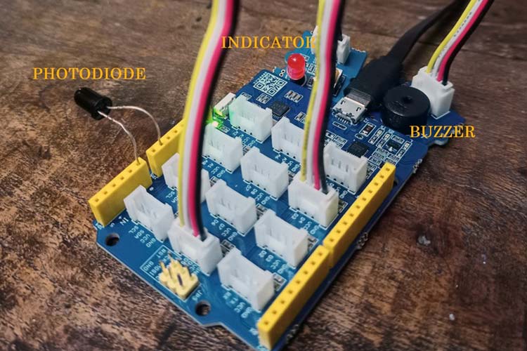
The power supply receives an unregulated dc power supply from the outside, preferably a battery, and creates voltage levels with ample amount of current for different components. The sensor circuitry is responsible for sensing the flame. As we know, that fire emits infrared radiations(700 nm to 1 mm), we use photodiodes to measure peak wavelengths of around 650nm. With having 6 of them placed for omnidirectional sensing. An analog multiplexer, multiplex these signals and sends it to the MCU. The Main Control Unit (MCU) is the brain of the system. It interfaces with the sensor circuit by addressing the analog multiplexer since it has only one ADC. After reading the signals from the 6 sensors, it computes centroid and approximates the position of the burning fire. And after moving towards the fire, it switches to PID control to navigate the robot near to the fire. Then it actuates the relay. Along with that, it has WiFi so that it can be connected to the network and act as a thing of IoT. It can notify you about the mishap instantly. Thus being a major player in critical situations like fire. And last but not the least, the driver circuit, which as the name suggests drives or actuates by receiving the control signal from the MCU. It can drive four to eight motors for the movement of an autonomous robot. It also contains a relay that can actuate any high power element such as a water pump to push water, or a strong electromagnet, or a solenoid to trigger a fire extinguisher. For software, EasyEda was used to design the PCBs, and to develop the firmware we used Arduino IDE.
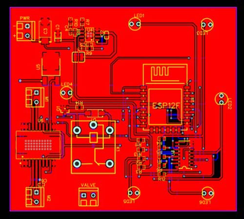
Fire Fighting Bot Controller Circuit Diagram

The Screw Terminal is given for a battery input source, then it is fed into a 5v voltage regulator that regulates the input voltage to fixed 5v, then there is an L298 motor driver to drive the motors upon the signals coming through the microcontroller ESP12F wifi microcontroller. Here we have 5 photodiodes placed omni directionally to sense the fire from all directions. And along with that, it has got a relay, that can switch high power motors or valves to extinguish the fire.
Challenges
We ran into Among the challenges we faced, one of the mentionable ones was understanding how to proceed with the circuit without using a microcontroller. Another challenge that we took upon ourselves was simplifying the circuit to a great extent for very optimized results and very low power consumption. Last but not least, routing the PCB in a very small area was also quite challenging.
Accomplishments
Accomplishments that we're proud of Coming up with a very inexpensive design to such was one of our accomplishments. We were also very happy for being able to create and complete the entire PCB on time.
What we will learn?
We learned a lot about digital and analog circuitry. And along with that, we also learned about different components while designing the PCB.
What's next for Fire Fighting Bot
In the future, we would like to create a pathway for the circuitry to notify the owner as well as the Fire and Emergency services nearby, on the instance of a fire breaking out at the location using IoT.
Complete Project Code
void setup()
{
Serial.begin(9600);

DDRB|=0xff;
PORTB=0x00;

pinMode(A0, INPUT_PULLUP);
}

float x=0;
int x[4], y[4];
int n=4;

void loop()
{
x=0.5*analogRead(A0) + 0.5*x;
Serial.println(x);

for(byte addr=0;addr<7;addr++)
{
  PORTB=addr;
  x[addr]=analogRead(A0);
  y[addr]=analogRead(A0)&(addr&2|addr&3|addr&4|addr&5);
}
  centroid();
if(cx&&cy<300)
alarm();

else
{
digitalWrite(3, LOW);
digitalWrite(5, LOW);
}

}

void alarm()
{
for(int i=0;i<256;i++, delay(4))
{
analogWrite(3, i);
analogWrite(5, i);
}

for(int i=255;i>0;i--, delay(4))
{
analogWrite(3, i);
analogWrite(5, i);
}

}


void centroid()
{
float a, cx, cy, t;
int i, i1;

a = 0.0;
i1 = 1;
for (i=0; i<n; i++) {
a += x[i] * y[i1] - x[i1] * y[i];
i1 = (i1 + 1) % n;
}
a *= 0.5;
cx = cy = 0.0;
i1 = 1;
for (i=0; i<n; i++)
{
t = x[i]*y[i1] - x[i1]*y[i];
cx += (x[i]+x[i1]) * t;
cy += (y[i]+y[i1]) * t;
i1 = (i1 + 1) % n;
}
cx = cx / (6.0 * a);
cy = cy / (6.0 * a);
}
