

The oscilloscope is a must-have test instrument for any electronics engineer. It is used to visualize and observe various signals, usually as a two-dimensional plot with one or more signals plotted against time. They are used in designing and debugging electronic devices to view and compare waveforms, and determine voltage levels, frequency, noise, and other parameters of signals applied at their input as they change with time. This makes oscilloscopes a very important tool on the desk of an electronics engineer or maker. Oscilloscopes, however, are quite pricey; entry-level models can cost anywhere from $500 to $2,000. And the advanced oscilloscopes cost a few thousand dollars, which puts them beyond the reach of basic users. But what if we could create one that is cheaper, compact, and easy to make? That is the question that led to this DIY ESP32 oscilloscope project. We have also built oscilloscopes through other channels, such as an oscilloscope using an Arduino Nano, a Raspberry Pi-based oscilloscope, and an oscilloscope using a Raspberry Pi Pico.
DIY Oscilloscope using ESP32 - Quick Overview
Build Time: 6-8 hours | Cost: $30-50 | Difficulty: Intermediate
What You'll Learn: ADC sampling, SPI communication, TFT display interfacing, Interrupt handling
Applications: Signal debugging, Waveform analysis, Frequency measurement, Voltage monitoring
Table of Contents
ESP32 Oscilloscope Features & Specifications
| Feature | Specification | Performance |
| Channels | Single-channel | Does the job for basic signal analysis |
| Sample Rate | 1Msps | great for audio, sensor, and low-frequency signal analysis |
| Buffer Size | 50000 @ 16bits | 50ms data capture at 1Msps |
| Time Scale | 10us/div to 5ms/div | Versatile timing options |
| Input Voltage | 3.3V (1X), 33V (10X) | Safe operating range |
| Response Time | Fast tactile control | Real-time signal monitoring |
| Frequency Range | 20Hz minimum | Limited by buffer constraints |
Key Features:
» It has a simple mean filter ON/OFF functionality
» Max, min, average, and Peak-Peak voltage measurements
» Time and voltage offset adjustments
» Analog and Digital/Data Mode operation
» Single TRIGGER capability
» AUTOSCALE function for automatic setup
Components Required for Your DIY ESP32 Oscilloscope Project
Component Requirements Table:
| Component | Specification | Quantity | Purpose |
| ESP32 Devkit | 38-pin variant recommended | 1 | The Main microcontroller |
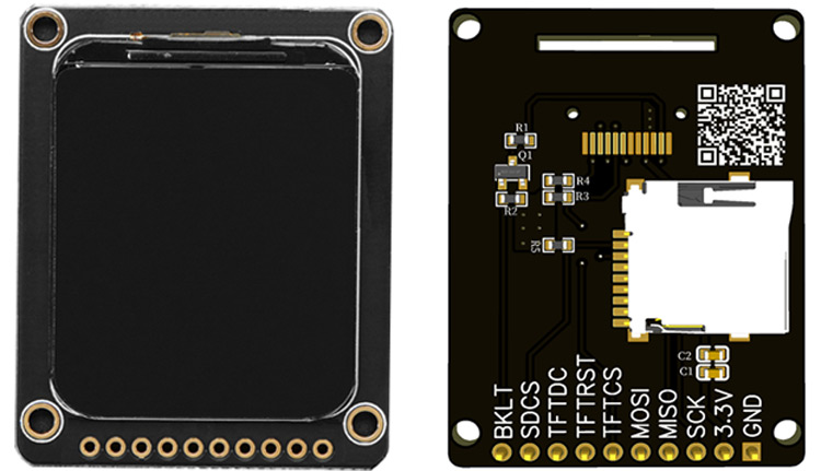
| TFT Display | 1.69" 240x280 ST7789s | 1 | Signal visualization |
| Tactile Switches | Standard 6mm | 6 | User interface control |
| SPDT Switches | Toggle type | 2 | Range/coupling selection |
| Resistors | 100K, 10K | 1 each | Input conditioning |
| Capacitor | 100nF ceramic | 1 | AC coupling |
| PCB/Perfboard | Copper clad | 1 | Circuit assembly |
DIY Oscilloscope Schematic Design & Circuit Analysis
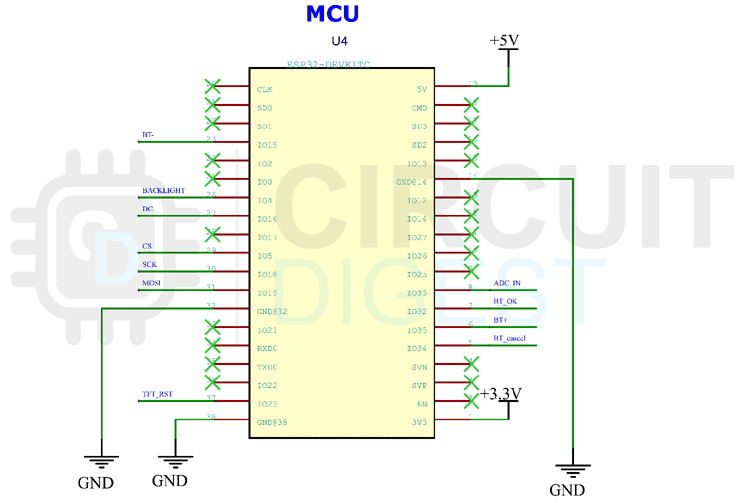
The complete DIY oscilloscope schematic is given below.

Circuit Design Breakdown:
ESP32 is used as the controller for the data acquisition. We will be utilizing the built-in I2S buffer to store and manipulate the signals. Here, the 38 Pin variant is used, but you can also use other development modules too.
Display Interface & Communication Protocol
For display, we are using a 1.69” TFT display module. It has a resolution of 240x280 pixels. The display controller (ST7789S) communicates via SPI protocol, ensuring fast screen updates essential for real-time waveform visualization.
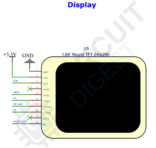
Display Features:
» High-resolution waveform rendering
» Real-time signal updates
» Integrated SD card slot for future data logging
» The design keeps power consumption to a minimum
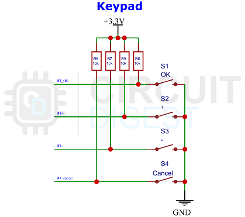
User Interface Design for the ESP32 Oscilloscope
The Keypad is very simple. Tactile switches with pull-up resistors are used for this purpose. We are using the hardware interrupt to detect each key press. This will give us a very responsive keypad. You can learn about ESP32 Interrupts that we covered previously.
Input Signal Conditioning Circuit
The analog input section is fairly simple. It consists of two SPDT switches for range selection and AC/DC coupling selection. For range selection, we have added a voltage divider that can be used to feed signals with a peak voltage higher than 3.3V. The voltage divider will convert the signal to a 10:1 ratio.
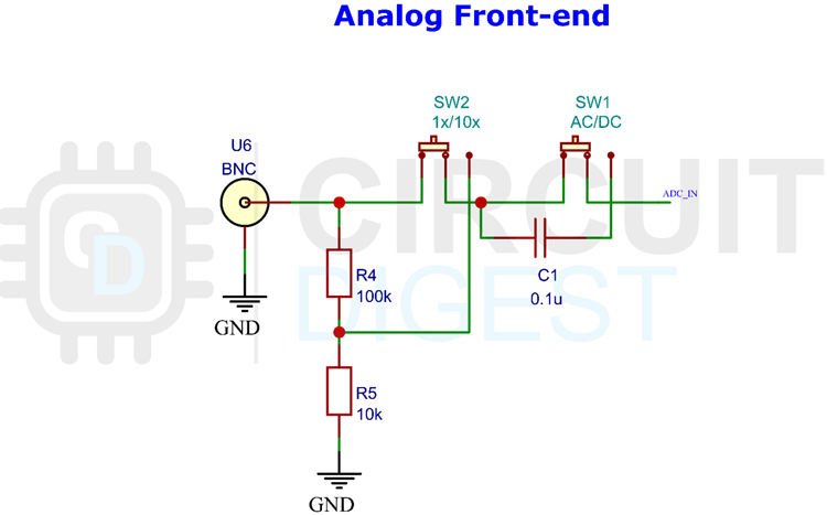
Input Circuit Features:
» Dual-range voltage measurement (3.3V and 33V)
» AC/DC coupling selection
» Input protection circuitry
» Precision voltage division
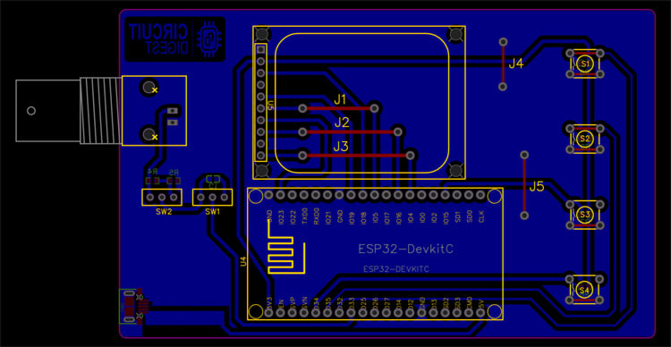
PCB Design & Assembly Guide for ESP32 Oscilloscope Project
You can either build this project in a perfboard or you can make a PCB with the files from the link at the bottom of the page. Both PDF files for the toner transfer method and the Gerber file for the manufacturing are included.
PCB Design Considerations:
» Optimized signal routing for minimal noise
» Compact form factor design
» Easy component accessibility
» Compatible for professional manufacturing
Here is the PCB layout for the Oscilloscope.
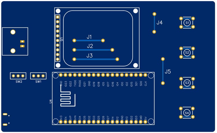
And here is the PCB view for the same.
Assembly Process:
» Component placement verification
» Soldering sequence optimization
» Signal path testing
» Calibration procedures
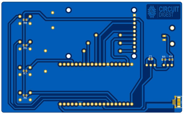
Bottom side PCB view.
Programming Your DIY ESP32 Oscilloscope
Programming Steps:
» Library Installation: Extract the modified TFT_eSPI library to Arduino libraries folder
» Board Selection: Choose ESP32 in Arduino Board Manager
» Code Compilation: Verify code compilation without errors
» Upload Process: Flash firmware to ESP32 via USB
» Power Configuration: Use Micro USB port for 5V power supply
Code Features:
» Optimized I2S buffer management
» Real-time waveform rendering
» Interrupt-driven user interface
» Calibration routines
» Signal processing algorithms
GitHub Repository
Download the entire code from the Circuit Digest GitHub repo link given at the bottom of this article. In the GitHub repo, you can also find an archive named TFT_eSPI. This modified library is necessary to drive the display. Extract it to the Arduino library folder. If you have already installed the TFT_eSPI library, make sure to remove it before extracting the modified one. Once it’s done, select ESP32 in the board manager. Then compile the code and upload it. That’s it, our DIY Oscilloscope is ready to use. You can power the Oscilloscope using the Micro USB port at the bottom. This port is only for power.


Common Questions About This ESP32 Oscilloscope Project
Q1. Can this replace a real oscilloscope?
Not really. A commercial DSO (Rigol, Siglent, etc.) can sample hundreds of times faster and has deep memory, multiple channels, and accurate front-ends. This ESP32 version is more of a “learning scope”, great for audio, sensors, and slow digital signals, but it won’t catch high-speed glitches or MHz bus activity.
Q2. What’s the safe input range?
With the voltage divider, you can look at signals up to around 33 V peak. Without it, the ESP32 only tolerates 3.3 V max. Do not connect this directly to mains (120/230 V AC) or anything high-energy. It’s not isolated, and you’ll fry the board (or yourself).
Q3. Why does the waveform look noisy or a bit “jagged”?
That’s just the ESP32’s ADC. It’s not lab-grade. There’s quantization noise and some non-linearity. The mean filter helps, but you should expect “good enough” plots, not razor-clean signals like you’d see on a Tektronix.
Q4. What’s the highest frequency signal I can measure?
Think in the tens of kHz, maybe low hundreds if you’re not picky about accuracy. The 1 Msps sample rate and buffer size limit the bandwidth. It’s fine for PWM, audio, and sensor data. Not for RF or fast digital buses like SPI or USB.
Q5. Is it actually “real-time”?
Sort of. The display updates fast enough that it feels live for slow and mid-speed signals. But compared to a commercial scope, there’s noticeable lag and the capture depth is shallow. It’s real-time enough for hobby work, not for debugging a complex circuit.
Related ESP32 & Arduino Projects
Advance your skills with hands-on electronics builds that push the limits of microcontrollers, from measuring real-world power efficiency to generating custom waveforms and even streaming audio playback.

Arduino and ESP32 Based Power Meter
Here we built an ESP32 energy monitor to measure input and output power for calculating power efficiency.

AD9833 and Arduino Based Function Generator
In this article we are going to build a simple Signal Generator with Arduino and AD9833 DDS Function Generator Module which can produce sine, square, and triangle waves with a maximum frequency of 12 MHz at the output.

Here we use LM386 and a speaker with ESP32 to play music files. The audio output may not be loud but this application shows the ability of the ESP32 board to play audio files.
Complete Project Code
#include <Arduino.h>
#include <driver/i2s.h>
#include <driver/adc.h>
#include <soc/syscon_reg.h>
#include <TFT_eSPI.h>
#include <SPI.h>
#include "esp_adc_cal.h"
#include "filters.h"
//#define DEBUG_SERIAL
//#define DEBUG_BUFF
#define DELAY 1000
// Width and height of sprite
#define WIDTH  240
#define HEIGHT 280
#define ADC_CHANNEL   ADC1_CHANNEL_5  // GPIO33
#define NUM_SAMPLES   1000            // number of samples
#define I2S_NUM         (0)
#define BUFF_SIZE 50000
#define B_MULT BUFF_SIZE/NUM_SAMPLES
#define BUTTON_Ok        32
#define BUTTON_Plus        15
#define BUTTON_Minus        35
#define BUTTON_Back        34
TFT_eSPI    tft = TFT_eSPI();         // Declare object "tft"
TFT_eSprite spr = TFT_eSprite(&tft);  // Declare Sprite object "spr" with pointer to "tft" object
esp_adc_cal_characteristics_t adc_chars;
TaskHandle_t task_menu;
TaskHandle_t task_adc;
float v_div = 825;
float s_div = 10;
float offset = 0;
float toffset = 0;
uint8_t current_filter = 1;
//options handler
enum Option {
  None,
  Autoscale,
  Vdiv,
  Sdiv,
  Offset,
  TOffset,
  Filter,
  Stop,
  Mode,
  Single,
  Clear,
  Reset,
  Probe,
  UpdateF,
  Cursor1,
  Cursor2
};
int8_t volts_index = 0;
int8_t tscale_index = 0;
uint8_t opt = None;
bool menu = false;
bool info = true;
bool set_value  = false;
float RATE = 1000; //in ksps --> 1000 = 1Msps
bool auto_scale = false;
bool full_pix = true;
bool stop = false;
bool stop_change = false;

uint16_t i2s_buff[BUFF_SIZE];

bool single_trigger = false;
bool data_trigger = false;

bool updating_screen = false;
bool new_data = false;
bool menu_action = false;
uint8_t digital_wave_option = 0; //0-auto | 1-analog | 2-digital data (SERIAL/SPI/I2C/etc)
int btnok,btnpl,btnmn,btnbk;
void IRAM_ATTR btok()
{
  btnok = 1;
}
void IRAM_ATTR btplus()
{
  btnpl = 1;
}
void IRAM_ATTR btminus()
{
  btnmn = 1;
}
void IRAM_ATTR btback()
{
  btnbk = 1;
}
void setup() {
  Serial.begin(115200);

  configure_i2s(1000000);

  setup_screen();

  pinMode(BUTTON_Ok , INPUT);
  pinMode(BUTTON_Plus , INPUT);
  pinMode(BUTTON_Minus , INPUT);
  pinMode(BUTTON_Back , INPUT);
  attachInterrupt(BUTTON_Ok, btok, RISING);
  attachInterrupt(BUTTON_Plus, btplus, RISING);
  attachInterrupt(BUTTON_Minus, btminus, RISING);
  attachInterrupt(BUTTON_Back, btback, RISING);

  characterize_adc();
#ifdef DEBUG_BUF
  debug_buffer();
#endif

  xTaskCreatePinnedToCore(
    core0_task,
    "menu_handle",
    10000,  /* Stack size in words */
    NULL,  /* Task input parameter */
    0,  /* Priority of the task */
    &task_menu,  /* Task handle. */
    0); /* Core where the task should run */

  xTaskCreatePinnedToCore(
    core1_task,
    "adc_handle",
    10000,  /* Stack size in words */
    NULL,  /* Task input parameter */
    3,  /* Priority of the task */
    &task_adc,  /* Task handle. */
    1); /* Core where the task should run */
}


void core0_task( void * pvParameters ) {

  (void) pvParameters;

  for (;;) {
    menu_handler();

    if (new_data || menu_action) {
      new_data = false;
      menu_action = false;

      updating_screen = true;
      update_screen(i2s_buff, RATE);
      updating_screen = false;
      vTaskDelay(pdMS_TO_TICKS(10));
      Serial.println("CORE0");
    }

    vTaskDelay(pdMS_TO_TICKS(10));
  }

}

void core1_task( void * pvParameters ) {

  (void) pvParameters;

  for (;;) {
    if (!single_trigger) {
      while (updating_screen) {
        vTaskDelay(pdMS_TO_TICKS(1));
      }
      if (!stop) {
        if (stop_change) {
          i2s_adc_enable(I2S_NUM_0);
          stop_change = false;
        }
        ADC_Sampling(i2s_buff);
        new_data = true;
      }
      else {
        if (!stop_change) {
          i2s_adc_disable(I2S_NUM_0);
          i2s_zero_dma_buffer(I2S_NUM_0);
          stop_change = true;
        }
      }
      Serial.println("CORE1");
      vTaskDelay(pdMS_TO_TICKS(300));
    }
    else {
      float old_mean = 0;
      while (single_trigger) {
        stop = true;
        ADC_Sampling(i2s_buff);
        float mean = 0;
        float max_v, min_v;
        peak_mean(i2s_buff, BUFF_SIZE, &max_v, &min_v, &mean);

        //signal captured (pp > 0.4V || changing mean > 0.2V) -> DATA ANALYSIS
        if ((old_mean != 0 && fabs(mean - old_mean) > 0.2) || to_voltage(max_v) - to_voltage(min_v) > 0.05) {
          float freq = 0;
          float period = 0;
          uint32_t trigger0 = 0;
          uint32_t trigger1 = 0;

          //if analog mode OR auto mode and wave recognized as analog
          bool digital_data = !false;
          if (digital_wave_option == 1) {
            trigger_freq_analog(i2s_buff, RATE, mean, max_v, min_v, &freq, &period, &trigger0, &trigger1);
          }
          else if (digital_wave_option == 0) {
            digital_data = digital_analog(i2s_buff, max_v, min_v);
            if (!digital_data) {
              trigger_freq_analog(i2s_buff, RATE, mean, max_v, min_v, &freq, &period, &trigger0, &trigger1);
            }
            else {
              trigger_freq_digital(i2s_buff, RATE, mean, max_v, min_v, &freq, &period, &trigger0);
            }
          }
          else {
            trigger_freq_digital(i2s_buff, RATE, mean, max_v, min_v, &freq, &period, &trigger0);
          }

          single_trigger = false;
          new_data = true;
          Serial.println("Single GOT");
          //return to normal execution in stop mode
        }

        vTaskDelay(pdMS_TO_TICKS(1));   //time for the other task to start (low priorit)

      }
      vTaskDelay(pdMS_TO_TICKS(300));
    }
  }
}
void loop() {}
Comments
This is a very nice project. I am going to build and use.
I have a breadboard up and running the code with one problem.
I am using the ESP32 D1 mini board (with limited GPIO)
The analog port of the project code is not availible (ADC1_CHANNEL05 GPIO33)
I have changed to: #define ADC_CHANNEL ADC1_CHANNEL_0 // GPIO36
The measurement of frequency and voltage (pp) on the display is ok
B U T I have no oscilloscop signal.
What must I do to fix this problem?
I had the same problem, when menu was activated I got Vmax: -6.42V and Vmin: -6.6V
1. Function ADC_Sampling have to be changed to:
void ADC_Sampling(uint16_t *i2s_buff){
size_t bytes_read; for (int i = 0; i < B_MULT; i++) {
i2s_read(I2S_NUM_0, (void*)&i2s_buff[i * NUM_SAMPLES], NUM_SAMPLES * sizeof(uint16_t), &bytes_read, portMAX_DELAY);
for(size_t ix = 0; ix < bytes_read/2; ix++) i2s_buff[(i * NUM_SAMPLES) + ix] &= 0x0FFF; // 16bit to 12bit conversion
}
}
2. Functions in screen.ino have to be corrected as well:
float to_scale(float reading) {
float temp = WIDTH - (((reading / 4095.0) + (offset / 3.3)) * 3300 / (v_div * 6)) * (WIDTH - 1) - 1; return temp;
}
float to_voltage(float reading) { return reading / 4095.0 * 3.3; }
uint32_t from_voltage(float voltage) { return ((uint32_t)(voltage / 3.3 * 4095)) ; }
The same problem here. Code is running on display but no oscilloscope signal.
I have put a question on the forum. No answers yet.
Hi guy,
It seems to be a really nice project. I wonder if I can put a bigger LCD to be more comfortable.
Cheers
Will you please Guide how to upload the code??
Hi all.
Can this project be used on TTGOS3? or with a external DAC if need?
Thanks.
I presume my noob-bench is surrounded by devices containing analog waveform sources using a compatible voltage, but I'm reluctant to open then up to my new un-tested scope. Can you recommend a simple demo/test setup (signal source) for breadboard?
Hi,
Has anyone else ad this error when compiling?
Compilation error: 'ADC_ATTEN_11db' was not declared in this scope; did you mean 'ADC_ATTEN_DB_6'?
These are the two lines that are causing problems in i2s.ino tab
Try to use the v 2.x.x of the ESP32 board manager. The newer version(3.x.x) has a lot of code-breaking changes.
I am unable to compile and use your code with Arduino 2.3.4. Much of the code shows errors.
Can you give me a newer version that works?
thanks.
Use the ESP board manager with version 2.x.x. Don't use the latest 3.x.x.
Compilation error: 'i2s_read_bytes' was not declared in this scope
i2s_read_bytes(I2S_NUM_0, (char*)&i2s_buff[i * NUM_SAMPLES], NUM_SAMPLES * sizeof(uint16_t), portMAX_DELAY);
Compilation error: 'pgm_read_bytes' was not declared in this scope
Compilation error: 'configure_i2s' was not declared in this scope
Use the ESP board manager with version 2.x.x. Don't use the latest 3.x.x.
Please tell me from where we can find this display or what are there substitute
Search for a 1.69” TFT display with a resolution of 240x280 pixels and ST7789S controller. If you are buying a module , the pinout might be different. So change the connections accordingly.
I have submitted this project for my project also submitted project report in my college but now I unable to find this display please tell is any possible way to buy this project.
Location delhi india
As said in the earlier comment you can get 1.69" display with the said controller and use it. only difference might be the pinout. so change that accordingly.
To compile, use -
ESP32 Dev Module
ESP32 = 1.0.6

In the code it says '//TODO i2s_read_bytes is deprecated, replace with new function'
Did you ever get to writing a new function with that because I'm not entirely sure how to go about doing that so that I can get input
Many Thanks,
Nic