

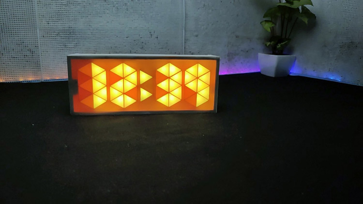
I know making a clock sounds a little irrelevant, especially nowadays because we all have smartphones and no one is going to use or look into the clock for time, but it is good when you are doing some work or during the workout. So, I decided to make one Arduino digital clock for my room. While searching for the clock model, I got thousands of designs but most of them were using seven-segment displays and I wanted to build a unique and colorful clock without using Seven segment display. So, here I am going to use Neo-Pixel LEDs with Arduino pro mini and RTC module. About the clock I made, it's a very simple clock that shows time and room temperature and the main feature of this clock is that the color of the digits changes every minute.
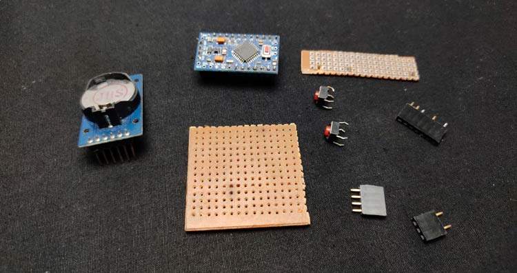
Components to build your own Rainbow Clock
- Arduino Pro Mini
- DS3231 RTC Module
- WS2812 Neo pixel LEDs- 42nos
- 2× Push Button Switches
- AMS1117 Voltage Regulator
- Perf Board
- Connecting Wires
- 330-ohm Resistor
- MDF sheet
Arduino 10 Segment Rainbow Clock Working
The working of this clock is very simple and similar to other digital clocks. This clock gets the current time and date using the DS3231 RTC module and then this time is displayed on Neo-Pixel LEDs using Arduino Pro Mini. The DS3231 is a low-cost, accurate Real Time Clock that can maintains hours, minutes, and seconds, as well as, day, month, and year information. The module uses the I2C communication protocol which makes the connection to the Arduino board very easy. However, when it comes to communication between Arduino and RTC module the code isn’t that small and easy. But there are already several libraries for the DS3231 RTC which can be found on the internet. with the help of such libraries, we can read the current time, and with the help of Arduino, we can display that time in any type of display. DS3231 RTC module also comes with a temperature sensor so, we can also get the temperature readings.
Ten Segment Rainbow Clock Circuit Diagram
The complete schematic for building Arduino LED Clock is shown in the image given below:

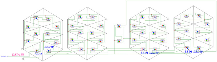
As you can see, this circuit diagram has two parts, first one is the main circuit that consists of an Arduino Pro Mini, DS3231 RTC module, push buttons, and AMS1117 voltage regulator and the second is the LED digit circuit where all the Neo-Pixel LEDs are arranged to display the time. DS3231 works on the I2C communication protocol so the SCL and SDA pins of the RTC module are connected to I2C pins (A4 and A5) of Arduino. The push buttons are connected to digital pin 2 and 4 of Arduino. This complete setup is powered by two 18650 cells connected in series. The output voltage from these cells will be around 7.4 so an AMS1117 5V voltage regulator is used to supply regulated 5V to Arduino pro mini and other components.
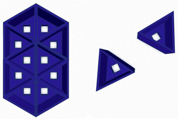
3-D Printing the Parts to Display Time
As discussed earlier, instead of using a 7-segment display we are going to use Neo-Pixel LEDs for displaying time. Here, we are going to 3-D print some parts so that we can arrange the Neo-Pixel LEDs in digits form and display time. After hours of thinking and calculations, I designed a ten-segment digit. The design is very simple, each segment has a slot for Neo pixel LED. Later in these slots, we will place Neo pixel LEDs. I also designed two segments for the second indication. I have designed all the parts in Tinker CAD software. Once it was done, my design looked something like this:
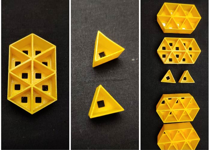
After I was satisfied with the design, I exported it as an STL file, sliced it based on printer settings, and finally printed it. The STL file is also available for download from Thingiverse and you can print your casing using it.
Assembling the Neo-Pixel LEDs on 3-D Printed Parts
![]()
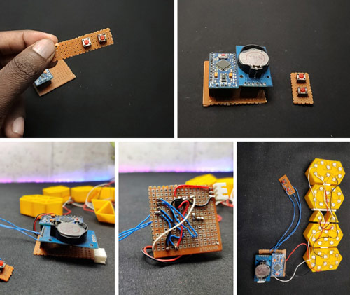
After 3D printing of the parts, first, we need to insert the Neo-pixel LEDs on their respective sockets. A Neo-pixel LED has 4 pins that are VCC, GND, data IN, and data Out. To control a Neo-pixel LED, we should feed the signal to the din pin. We can connect multiple LEDs by connecting the Data OUT pin to the Data IN pin of the next LED and so on. Here, take a WS2812 Neo-pixel and insert it into the socket. Do the same for the 10 segments, remember to place the LEDs in the same orientation. After placing the LEDs let's start soldering. First, solder all the grounds of 10 LEDs together. For this, I am using single-stranded copper wire. Check the pins of each LED before soldering. Also, don't apply more heat on the LED. After connecting all grounds, now let's connect all VCC pins together. Next, connect the first data out to the data in the pin of the next LED. Repeat this for all the ten LEDs. After finishing all the soldering, we will get a common ground, common 5v, data in connection for the first LED, and data out the wire from the last LED. We have to repeat this process for the remaining 3 digits. Also, insert two LEDs in the second segment and solder. After connecting all the digits and the second segment, let's connect digits together. Connect first digit (from left-hand side) data out to the din in of the second digit then data out of second to the din of third and so on finally connect the last digit out to the data in of the second segment. connect all the 5 v together and also the grounds. That's it, now we have a common ground, a common 5v, and a din.
Building the Circuit on Perf Board
After testing the circuit on the breadboard, I decided to solder it permanently on a perf board. I tried to build the circuit as small as possible to reduce the size. First, I took a small piece of perf board, and then I placed the female header pin for the RTC module and Arduino pro mini. Next, I placed the push buttons on an even small perf board and soldered its pins to the perf board. Then with the help of flexible wire, I attached the push buttons to the main PCB.
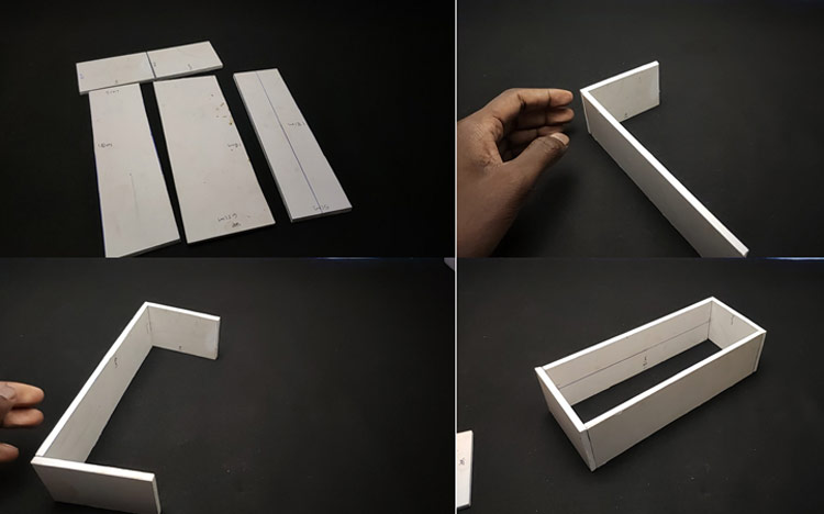
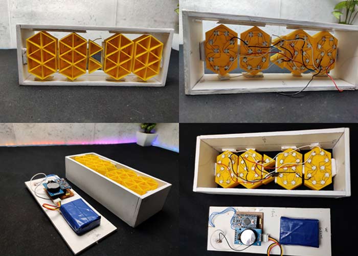
Building the Enclosure for Ten Segment Rainbow Clock
This is not the hardest part. Either you can 3D print the enclosure or make it yourself. So, first I measured the length and width of the digits. After getting the measurement, I took a 5mm MDF board and drawn sides of rectangles having a length of 18cm and a width of 6.5mm. I plan to build a rectangular structure and place the digits in it. After drawing the lines, I cut the rectangles using the cutter and joined them together, and made a rectangular structure without a front. If you are confused with the making, you can refer to the images. After building the frame, I inserted the digits into the frame and secured it with glue. On the backside of the frame, I fixed the main circuit and battery. Also, I placed the pushbuttons and the on/off switch on the outer backside. After connecting the digits with the main circuit, I closed the backside. Finally, we need to attach a plastic sheet to the front side of the clock for better light diffusion. You can use any type of diffused plastic sheet.
Programming Arduino Pro Mini for Rainbow Clock
As I mentioned earlier, the code for this project is not very simple. Honestly, I referred to lots of other clock projects to make this code. Whatever, the complete code is given at the end of the document. Here, I am explaining the complete code line by line.
First, I included the required libraries. In this project, we are using the ds3231 RTC library to control the DS3232RTC module. DS3232RTC is an Arduino library that supports the Maxim Integrated DS3232 and DS3231 Real-Time Clocks. The DS3232RTC library also implements functions to support the additional features of the DS3232 and DS3231. Time and Timelib libraries provide timekeeping functionality for Arduino. Wire library allows communication with I2C(DS3231) devices. And finally, I am using FastLED to control the neopixel LEDs
#include <DS3232RTC.h>
#include <TimeLib.h>
#include <Time.h>
#include <Wire.h>
#include <FastLED.h>
Next, I defined the total number of LEDs, colour order of LED type, Arduino pin for data input, and push-button pins.
#define NUM_LEDS 42
#define COLOR_ORDER RGB
#define LED_PIN 6
#define MIN_PIN 4
#define HUR_PIN 2
Also, I made a byte array for the numbers and symbols. We have a total of 10 LEDs in each digit and a total of 12 characters (0-9 numbers + Degree symbol and C letter) each array represents each character. For example {1,1,0,1,1,1,1,0,1,1} represents zero that is in our digit segment 3 and segment 8 in off-stage all other LEDs in on stage that will display zero and so on…
byte digits[12] [10] = {
{1,1,0,1,1,1,1,0,1,1},
{1,1,1,1,1,0,0,0,0,0},
{1,0,1,1,1,1,0,1,1,1},
{1,1,1,1,1,1,0,1,0,1},
{1,1,1,1,0,1,1,1,0,0},
{1,1,1,0,1,1,1,1,0,1},
{1,1,1,0,0,1,1,1,1,1},
{1,1,1,1,1,1,1,0,0,0},
{1,1,1,1,1,1,1,1,1,1},
{1,1,1,1,1,1,1,1,0,0},
{1,1,1,1,1,1,1,1,0,0},
{0,0,1,1,1,1,1,1,0,0}};
Next, I defined the color table you can customize this according to your ideas.
 long ColorTable[21] = {
CRGB::Amethyst, //white
CRGB::Aqua, //pink
CRGB::Blue, //Blue
CRGB::Chartreuse,// Gold
CRGB::DarkGreen, //Red
CRGB::DarkMagenta,//Aqua
CRGB::DarkOrange, // yellow green
CRGB::DeepPink, //Aqua
CRGB::Fuchsia, //Sea blue
CRGB::Gold, //Gold
CRGB::GreenYellow,//off white
CRGB::LightCoral,//white
CRGB::Tomato,//white
CRGB::Salmon,//Pure white
CRGB::Red,// Drak Green
CRGB::Orchid,//blue white
CRGB::Sienna,//yellow white
CRGB::Purple,// aqua
CRGB::DarkOrange,//yellow green
CRGB::FloralWhite,//white
CRGB::Yellow //yellow
};
In the setup section first, I started the serial monitor and I2C communication using serial.begin and wire.begin respectively. Here, we use the serial monitor for testing the code and circuit. Also, I defined the mode of all pins here we are using button pins are as input and data pin as output and in the case of input, I used the input pull-up function to pull high pin status.
void setup(){
Serial.begin(9600);
Wire.begin();
FastLED.addLeds<WS2812B, LED_PIN, RGB>(leds, NUM_LEDS);
pinMode(DST_PIN, INPUT_PULLUP);
pinMode(MIN_PIN, INPUT_PULLUP);
pinMode(HUR_PIN, INPUT_PULLUP);
}
Then I read the time using the RTC.read function and stored it into a DateTime object. Also, I converted the 24-hour format into a 12-hour format.
GetTime(){
tmElements_t Now;
RTC.read(Now);
int hour=Now.Hour;
int minute=Now.Minute;
int second =Now.Second;
if (second % 2==0)
{Dot = false;}
else {Dot = true;};
if (hour >= 12) {
hour -= 12;
}
Next, I defined two arrays that are timetoarray and temptoarray for displaying the current time and temperature in the display. I started from the last LED of digits and displayed 4 digits. I defined the first LED of each digit using the cursor function. In the same way, I displayed the temperature also.
for(int i=1;i<=4;i++){
int digit = Now % 10;
if (i==1){
cursor = 30;
for(int k=0; k<=9;k++){
if (digits[digit][k]== 1){leds[cursor]=ledColor;}
else if (digits[digit][k]==0){leds[cursor]=0x000000;}
cursor ++
};
In the void time function, we can set the time. Here, I used the digital read function of Arduino to read the state of the pushbutton.
void TimeAdjust(){
int buttonH = digitalRead(HUR_PIN);
int buttonM = digitalRead(MIN_PIN);
if (buttonH == LOW || buttonM == LOW){
delay(500);
tmElements_t Now;
RTC.read(Now);
int hour=Now.Hour;
int minutes=Now.Minute;
int second =Now.Second;
if (buttonH == LOW){
if (Now.Hour== 23){Now.Hour=0;}
else {Now.Hour += 1;};
}else {
if (Now.Minute== 59){Now.Minute=0;}
else {Now.Minute += 1;};
};
RTC.write(Now);
}
Finally, in the main loop section, first I checked if the time is modified or not. Then, I updated the LED array according to the time. The same I did to the temperature array. Finally, I displayed the values in digits using fastLED.show function.
Void loop() {
BrightnessCheck();
DSTcheck();
TimeAdjust();
TimeToArray();
TempToArray();
FastLED.show();
if (TempShow == true)
delay (8000);
}
}
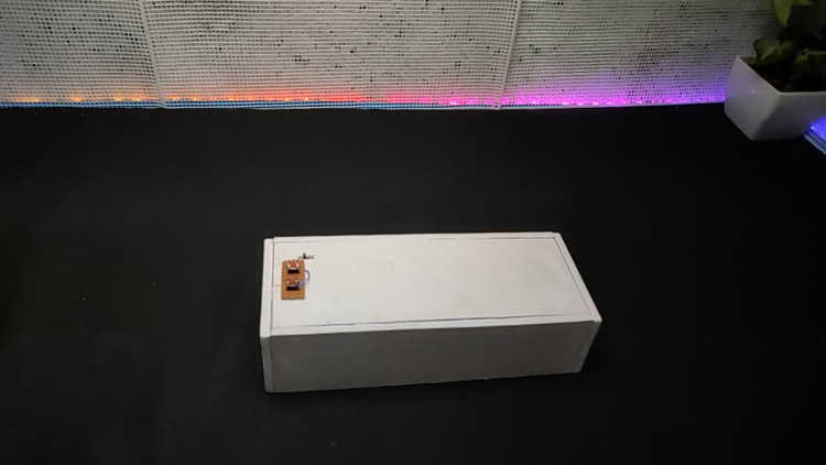
Testing our Ten Segment Rainbow Clock
Ok, so now we have assembled the Neo-Pixel LEDs and circuit. It’s time to test the clock. For that, connect the Arduino to laptop and upload the code.
I hope you liked this clock project. The complete making video is given below. If you have any questions, please, leave them in the comment section below.
Complete Project Code
#include <DS3232RTC.h>

#include <TimeLib.h>

#include <Time.h>

#include <Wire.h>

#include <FastLED.h>

#define NUM_LEDS 42

#define COLOR_ORDER RGB  // Define color order for your strip

#define LED_PIN 6 // Data pin for led comunication

#define DST_PIN 5  // Define DST adjust button pin

#define MIN_PIN 4  // Define Minutes adjust button pin

#define HUR_PIN 2  // Define Hours adjust button pin

#define BRI_PIN 3 // Define Light sensor pin

CRGB leds[NUM_LEDS];


byte digits[12][10] = {

  {1,1,0,1,1,1,1,0,1,1},

  {1,1,1,1,1,0,0,0,0,0},

  {1,0,1,1,1,1,0,1,1,1},

  {1,1,1,1,1,1,0,1,0,1},

  {1,1,1,1,0,1,1,1,0,0},

  {1,1,1,0,1,1,1,1,0,1},

  {1,1,1,0,0,1,1,1,1,1},

  {1,1,1,1,1,1,1,0,0,0},

  {1,1,1,1,1,1,1,1,1,1},

  {1,1,1,1,1,1,1,1,0,0},

  {1,1,1,1,1,1,1,1,0,0},

  {0,0,1,1,1,1,1,1,0,0}};


bool Dot = true;  //Dot state

bool DST = true; //DST state// false to true

bool TempShow = false;

int last_digit = 0;

// int ledColor = 0x0000FF; // Color used (in hex)

long ledColor = CRGB::DarkOrchid; // Color used (in hex)

//long ledColor = CRGB::MediumVioletRed;

//Random colors i picked up

long ColorTable[21] = {

  CRGB::Amethyst,  //white

  CRGB::Aqua,    //pink

  CRGB::Blue,     //Blue

  CRGB::Chartreuse,// Gold

  CRGB::DarkGreen, //Red

  CRGB::DarkMagenta,//Aqua

  CRGB::DarkOrange,  // yellow green

  CRGB::DeepPink,  //Aqua

  CRGB::Fuchsia,  //Sea blue

  CRGB::Gold,    //Gold

  CRGB::GreenYellow,//off white

  CRGB::LightCoral,//white

  CRGB::Tomato,//white

  CRGB::Salmon,//Pure white

  CRGB::Red,// Drak Green

  CRGB::Orchid,//blue white

  CRGB::Sienna,//yellow white

  CRGB::Purple,// aqua

  CRGB::DarkOrange,//yellow green

  CRGB::FloralWhite,//white

  CRGB::Yellow  //yellow

};

void setup(){

  Serial.begin(9600);

  Wire.begin();

  FastLED.addLeds<WS2812B, LED_PIN, RGB>(leds, NUM_LEDS);

  LEDS.setBrightness(75); // Set initial brightness

  pinMode(DST_PIN, INPUT_PULLUP); // Define DST adjust button pin

  pinMode(MIN_PIN, INPUT_PULLUP); // Define Minutes adjust button pin

  pinMode(HUR_PIN, INPUT_PULLUP); // Define Hours adjust button pin

  pinMode(BRI_PIN, INPUT_PULLUP); // Define bright adjust

  TempShow = false; // do not show temperature

}

// Get time in a single number, if hours will be a single digit then time will be displayed 155 instead of 0155

int GetTime(){

  tmElements_t Now;

  RTC.read(Now);

  //time_t Now = RTC.Now();// Getting the current Time and storing it into a DateTime object

  int hour=Now.Hour;

  int minute=Now.Minute;

  int second =Now.Second;

  if (second % 2==0)

   {Dot = false;}

    else {Dot = true;};

 if (hour >= 12) {

 hour -= 12;

  }

 // Handle hour 0 (midnight) being shown as 12.

  // else if (hour == 0) {

  // hour += 12;

  // }

     return (hour*100+minute);

  };

 // Check Light sensor and set brightness accordingly

void BrightnessCheck(){

  const byte sensorPin = 3; // light sensor pin

  const byte brightnessLow = 75; // Low brightness value

  const byte brightnessHigh = 20; // High brightness value

  int sensorValue = digitalRead(sensorPin); // Read sensor

  if (sensorValue == 0) {LEDS.setBrightness(brightnessHigh);}

  else {LEDS.setBrightness(brightnessLow);}

  };

// Convert time to array needed for display

void TimeToArray(){

  int Now = GetTime();  // Get time

  int cursor = 42; // last led number

  // Serial.print("Time is: ");Serial.println(Now);

  if (DST){   // if DST is true then add one hour

   Now+=100;

  // Serial.print("DST is ON, time set to : ");Serial.println(Now);

  };

  if (Dot){leds[40]=ledColor;

           leds[41]=ledColor;}

   else  {leds[40]=0x000000;

           leds[41]=0x000000;

    };

  for(int i=1;i<=4;i++){

    int digit = Now % 10; // get last digit in time

    if (i==1){

    //  Serial.print("Digit 4 is : ");Serial.print(digit);Serial.print(" ");

      cursor = 30;

      for(int k=0; k<=9;k++){

        // Serial.print(digits[digit][k]);

        if (digits[digit][k]== 1){leds[cursor]=ledColor;}

         else if (digits[digit][k]==0){leds[cursor]=0x000000;};

         cursor ++;

        };

      // Serial.println();
      if (digit != last_digit)

      {

        cylon();

        ledColor =  ColorTable[random(21)];

      }

      last_digit = digit;

      }

    else if (i==2){

      // Serial.print("Digit 3 is : ");Serial.print(digit);Serial.print(" ");

      cursor =20;

      for(int k=0; k<=9;k++){

        // Serial.print(digits[digit][k]);

        if (digits[digit][k]== 1){leds[cursor]=ledColor;}

         else if (digits[digit][k]==0){leds[cursor]=0x000000;};

         cursor ++;

        };

      // Serial.println();

      }

     else if (i==3){

      // Serial.print("Digit 2 is : ");Serial.print(digit);Serial.print(" ");

      cursor =10;

      for(int k=0; k<=9;k++){

        // Serial.print(digits[digit][k]);

        if (digits[digit][k]== 1){leds[cursor]=ledColor;}

         else if (digits[digit][k]==0){leds[cursor]=0x000000;};

         cursor ++;

        };

      // Serial.println();

      }

    else if (i==4){

      // Serial.print("Digit 1 is : ");Serial.print(digit);Serial.print(" ");

      cursor =0;

      if(digit !=0){

         for(int k=0; k<=9;k++){

        // Serial.print(digits[digit][k]);

        if (digits[digit][k]== 1){leds[cursor]=ledColor;}

         else if (digits[digit][k]==0){leds[cursor]=0x000000;};

         cursor ++;

        };

      }

      if(digit ==0){

      for(int k=0; k<=9;k++){

        // Serial.print(digits[digit][k]);

        if (digits[12][k]== 1){leds[cursor]=ledColor;}

         else if (digits[12][k]==0){leds[cursor]=0x000000;};

         cursor ++;

        };

      // Serial.println();

      }

    }

     Now /= 10;

  };

};

// Convert temp to array needet for display

void TempToArray(){

  tmElements_t tm;

  RTC.read(tm);

  if (tm.Second != 27) {

    TempShow = false;

    return;

  }

  TempShow = false;//true to false

  int t = RTC.temperature();

  int celsius = (t / 4.0) * 100;

  Serial.print("Temp is: ");Serial.println(celsius);

  int cursor = 42; // last led number

    leds[40]=0x000000;

    leds[41]=0x000000;

  for(int i=1;i<=4;i++){

    int digit = celsius % 10; // get last digit in time

    if (i==1){

      Serial.print("Digit 4 is : ");Serial.print(digit);Serial.print(" ");

      cursor = 30;

      for(int k=0; k<=9;k++){

        Serial.print(digits[11][k]);

        if (digits[11][k]== 1){leds[cursor]=ledColor;}

         else if (digits[11][k]==0){leds[cursor]=0x000000;};

         cursor ++;

        };

      Serial.println();

    }

    else if (i==2){

      Serial.print("Digit 3 is : ");Serial.print(digit);Serial.print(" ");

      cursor =20;

      for(int k=0; k<=9;k++){

        Serial.print(digits[10][k]);

        if (digits[10][k]== 1){leds[cursor]=ledColor;}

         else if (digits[10][k]==0){leds[cursor]=0x000000;};

         cursor ++;

        };

      Serial.println();

      }

    else if (i==3){

      Serial.print("Digit 2 is : ");Serial.print(digit);Serial.print(" ");

      cursor =10;

      for(int k=0; k<=9;k++){

        Serial.print(digits[digit][k]);

        if (digits[digit][k]== 1){leds[cursor]=ledColor;}

         else if (digits[digit][k]==0){leds[cursor]=0x000000;};

         cursor ++;

        };

      Serial.println();

      }

    else if (i==4){

      Serial.print("Digit 1 is : ");Serial.print(digit);Serial.print(" ");

      cursor =0;

      for(int k=0; k<=9;k++){

        Serial.print(digits[digit][k]);

        if (digits[digit][k]== 1){leds[cursor]=ledColor;}

         else if (digits[digit][k]==0){leds[cursor]=0x000000;};

         cursor ++;

        };

      Serial.println();

      }

    celsius /= 10;

  };

};

void DSTcheck(){

   int buttonDST = digitalRead(DST_PIN);

   // Serial.print("DST is: ");Serial.println(DST);

   if (buttonDST == LOW){

    if (DST){

      DST=false;

      // Serial.print("Switching DST to: ");Serial.println(DST);

      }

      else if (!DST){

        DST=true;

        // Serial.print("Switching DST to: ");Serial.println(DST);

      };

   delay(500);

   };

  }

void TimeAdjust(){

  int buttonH = digitalRead(HUR_PIN);

  int buttonM = digitalRead(MIN_PIN);

  if (buttonH == LOW || buttonM == LOW){

    delay(500);

    tmElements_t Now;

    RTC.read(Now);

    int hour=Now.Hour;

    int minutes=Now.Minute;

    int second =Now.Second;

      if (buttonH == LOW){

        if (Now.Hour== 23){Now.Hour=0;}

          else {Now.Hour += 1;};

        }else {

          if (Now.Minute== 59){Now.Minute=0;}

          else {Now.Minute += 1;};

         // if (Now.Hour > 12){Now.Hour = Now.Hour -12;}  // 24 to 12 hr

         // else {Now.Hour = Now.Hour ;};

          };

    RTC.write(Now);

    }

  }

/* coool effect function*/

void fadeall() { for(int i = 0; i < NUM_LEDS; i++) { leds[i].nscale8(250); } }

void cylon () {

  static uint8_t hue = 0;

  Serial.print("x");

  // First slide the led in one direction

  for(int i = 0; i < NUM_LEDS; i++) {

    // Set the i'th led to red

    leds[i] = CHSV(hue++, 255, 255);

    // Show the leds

    FastLED.show();

    // now that we've shown the leds, reset the i'th led to black

    // leds[i] = CRGB::Black;

    fadeall();

    // Wait a little bit before we loop around and do it again

    delay(10);

  }

  Serial.print("x");

  // Now go in the other direction.

  for(int i = (NUM_LEDS)-1; i >= 0; i--) {

    // Set the i'th led to red

    leds[i] = CHSV(hue++, 255, 255);

    // Show the leds

    FastLED.show();

    // now that we've shown the leds, reset the i'th led to black

    // leds[i] = CRGB::Black;

    fadeall();

    // Wait a little bit before we loop around and do it again

    delay(10);

  }

}

void loop()  // Main loop

{

  BrightnessCheck(); // Check brightness

  DSTcheck(); // Check DST

  TimeAdjust(); // Check to se if time is geting modified

  TimeToArray(); // Get leds array with required configuration

  TempToArray(); // Show Temperature

  FastLED.show(); // Display leds array

  if (TempShow == true)

  delay (8000);

}
Comments
Great project! Very nicely done. I have build one myself (similar), however, I am in the States. Would anyone know how to edit the code to read Fahrenheit (instead of Celsius)? I know, its a huge pain....why can't the US get with the metric system already??? LoL
I have tried many times and failed. I am using this same sketch, but using 86 leds. Would anyone be willing to help me figure this out? PLEASE
Thank you,
TM
Keep getting the message - 'RTC' was not declared in this scope- Why? Can you help me?
Hi,
I have tried many libraries and still get the error.
'RTC' was not declared in this scope
How to fix the Issue?
Thanks
Just need added DS3232RTC RTC;

Hi, huge compliment for your work, but I have a question: how can I test the display (0-9) as shown in the video?