
Hello! everyone, this tutorial will be extremely exciting for electronics makers because we will be designing our own touch-capacitive Piano with Arduino Nano. We will include a recording and replay feature on our Piano. So far, we've made a few piano projects using Arduino, but this one is quite different because we are going to use capacitive touch keys for our piano keys. So along with learning how to build a fun to play piano we will also explore how to design capacitive touch keys on PCB, as you can we have tried to make our keys looks as close an actual piano key. The PCB looks and works like a piano, thanks to its fabricator PCBWay, we will also explore how we designed and fabricated this board but before that, let's explore capacitive touch sensors and how it works.

How a Capacitive Touch Sensor Works?
We know that in order to form a capacitor with some capacitance value, we need two parallel conductive plates separated by a dielectric material. But how can we tell if the capacitance has changed simply by touching the conductive plate with our fingers? Our answer is based on our fundamental understanding of the capacitor. As we know, changing the area of the conductive plate or the distance between two parallel conductive plates can change the capacitance value. Between the conductive plate and the finger, we have air as a dielectric medium. As a result, when we touched the plate with our fingers, there was an uncertain increase in capacitance because our finger was acting as a conductive object and the distance between the two conductive objects was reduced. We know the basic formula of the capacitance of a parallel plate capacitor is,
C = ϵA/d
Where "A" is representing the area of the conducting plates, "d" is representing the distance between the two conductive plates and the "ϵ" is representing the permittivity of the AIR. As a result, increasing the area and decreasing the distance between the two parallel conductive plates increases the capacitance value. In our case, touching the conductive plate reduces the distance while increasing the capacitance value. Can we detect this changing capacitance by connecting a conductive material to a resistor and a microcontroller's GPIO pin? The answer is, we can't. Yes, connecting a voltage source to it will cause a small change in the analog voltage, but this is not a very robust solution.
How to Detect the Capacitance Change in a Capacitive Touch Sensor?
So, how could we tell if the capacitance value had changed? There is, however, a better way to go about it. Let's take a look at the block diagram below. Consider this to be a basic circuit consisting of a Microcontroller (in this case, an Arduino Nano), a 1 Mega Ohm resistor, and a Conductive Plate. The Arduino Nano's two digital lines are connected to a resistor loop with a 1 megaohm resistor. This resistor is also connected to the conductive plate at one point. Although this plate is acting as a single point of the capacitor, it can still introduce capacitance that changes when we touch it. This, however, cannot be detected simply by detecting a change in voltage. The change in capacitance on this line is not as easy as sensing the toggle of the on or off the value on the GPIO pin. The change in capacitance on this line is not as simple as sensing the toggle of the GPIO pin's value on or off.
How the Capacitive Sensor Library Works?
This is where the Arduino libraries come in handy. Thank you very much to Paul Bagder and Paul Stoffregen, the authors of the “CapacitiveSensor” library. When we touch that conductive plate, we can detect a change in capacitance using this library. One of the digital pins is used as a send pin (as OUTPUT), while the other is used as a receive pin (as INPUT) in this library. The duration between when the send pin goes high and when the receive pin goes high is the sole way to detect a change in capacitance. When you set the send pin to high (or 5 volts), the resistor-capacitor pair produces a delay between when the send pin becomes high and when the receive pin reads the high value from the send pin. The CapacitiveSensor library provides a function that sets the send pin to HIGH, then waits and counts until the receive pin is read as HIGH. This function returns a time value that can be used to detect capacitance changes. When the time value increases or decreases, it indicates that the capacitance value has changed. The receive pin will take longer to reach high when there is more capacitance, and it will take less time to go high when there is less capacitance. As a result, we can determine what the normal state is and then check for changes each time they send pin toggles.
We are going to use the “CapacitveSensor” library to detect the change in the capacitance. But before going into the programing part let’s create the circuit and PCB for our project. Here we are using the EasyEDA platform to create the Schematic and the PCB for our project. To detect the change in capacitance, we'll use the “CapacitveSensor” library. Let's start with the circuit and PCB for our project before we go into the programming. The Schematic and PCB for our project were created using the EasyEDA platform. On the EasyEDA platform, we've created a large number of PCB projects. Those projects can be used to obtain a concept of how to design a PCB on EasyEDA.
Components Required to build a PCB Piano using Arduino Nano
The following components are required to build a PCB Piano using Arduino Nano.
- Arduino Nano
- Resistors (1Mega Ohm) X 8
- Piezoelectric Buzzer
- 18650 Battery cell
- 18650 Battery cell holder
- 18650 battery Charging Module
- DC to DC Voltage Booster.
Circuit Diagram for the PCB Piano Using Arduino Nano
The eight 1Mega Ohm Resistors are connected to the Arduino Nano's digital pin number 2 in the following circuit diagram. The digital pins 3 to 10 were further connected to the other connecting points of each resistor. On the diagram below, we have a slide switch labelled "RECODINGSWITCH". The Arduino Nano's digital pin 12 is connected to the slide switch's "EN" pin. The slide switch's "Vs" pin is connected to the Arduino Nano's "5V" pin. The sliding switch's "GND" pin is connected to the Arduino Nano's "Ground Pin". The BUZZER's Positive pin is connected to the Arduino Nano's "A4" pin. And the negative of the BUZZER is connected to the Ground pin of the Arduino Nano.

We've connected eight 10uF capacitors to each of the resistors. And the negative pin of each capacitor is connected to the Arduino Nano's ground pin. Then we have a Power section that provides a proper 6.6V to the Arduino Nano's "Vin" pin. The 18650 battery cell is linked to the 18650 battery charger module, and the charger module's output is linked to the DC to DC Voltage booster. The voltage booster's positive output pin (BOUT+) is connected to the Arduino Nano's "Vin" pin, and the voltage booster's negative output pin (BOUT-) is connected to the Arduino Nano's ground pin.
Note: If necessary, we can add capacitors. Small capacitors (20pF - 400pF) are highly recommended for stabilizing detected data. However, ensure that the capacitors are grounded, as this reduces the parallel to the body resistance. However, in my case, I did not use the capacitors because it works fine for me without them. I mentioned the capacitors in the schematic above so you could easily add them during the practical implementation. The following capacitors' values must be between 20pF and 400pF, as specified in the “CapacitveSensor” library's documentation.
The Overview of the PCB
The PCB view of the above schematic is representing in the following picture below. You can download the Gerber File of the project from our GitHub Repo. Or, you can visit the project on EasyEDA platform for more details. The yellow color is for the Top-Silk Layer. Whereas the Green color is representing the bottom silk Layer. The Red Color is for the Top- Layer and the Blue color is representing the Bottom-Layer.

The Top-Layer of the PCB:
Now, let’s see every layer of the PCB one by one. The top-layer is shown in the image below. As you can see the Top-Layer is Red in color. I have designed each conductive plate in such a way that it looks like a piano. Every key of the piano is connected to each of the 1 megaohm resistors respectively.

I used the Rectangular shape that can be found in the PCB Tool section on the EasyEDA that is circled in red color in the image below. Make sure that the width of the keys is large enough so that you can touch each of the keys with your finger. In my case, I managed to draw every key having 10mm or greater than 10mm width.

The Bottom-Layer of the PCB:
At the bottom layer we have a complete copper layer that is used to connect all the grounds. You can use the “Solid Region” option in the “PCB Tools” on EasyEDA. This is called the “Copper Pouring” method. This step will convert the bottom layer as a common grounded layer. We have some other copper connections at this layer.

The Top-Silk-Layer of the PCB:
The following image below is representing the Top-Silk-Layer of the PCB. We can design our PCBs by adding some silk layers or Non-copper layers. I marked the slide switch as “RECORD” and “PLAY”. So that we can understand which mode we are using. We have the footprint of the BUZZER at the top silk layer. The “XL6009E1” is the footprint of the DC to DC voltage booster module surrounded by the square area. We can add text and images by using the respective PCB Tools which are available on the EasyEDA.

The Bottom-Silk-Layer of the PCB:
At the bottom silk layer of the PCB we have the footprint of the Arduino Nano, eight 1Mega ohm resistors, eight capacitors, one 18650 batter holder or single cell and the charging module.

Ordering PCB from PCBWay
Now after finalizing the design, you can proceed with ordering the PCB:
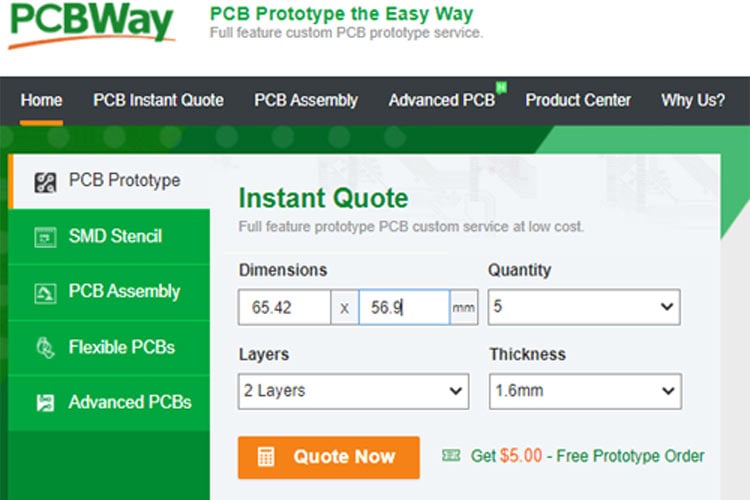
Step 1: Get into https://www.pcbway.com/, sign up if this is your first time. Then, in the PCB Prototype tab, enter the dimensions of your PCB, the number of layers, and the number of PCB you require.
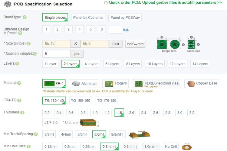
Step 2: Proceed by clicking on the ‘Quote Now’ button. You will be taken to a page where to set a few additional parameters like the Board type, Layers, Material for PCB, Thickness, and More, most of them are selected by default, if you are opting for any specific parameters, you can select it in here.
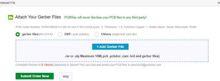
Step 3: The final step is to upload the Gerber file and proceed with the payment. To make sure the process is smooth, PCBWAY verifies if your Gerber file is valid before proceeding with the payment. This way, you can sure that your PCB is fabrication friendly and will reach you as committed.
After a few days, we received our PCB in a neat package and the PCB quality was good as always.

Program the Piano PCB Using Arduino Nano
The “CapacitiveSensor” library is really easy to use and they have provided such good documentation on how to use the library. Before get into the program let's install the “CapacitiveSensor” library on the Arduino IDE. You need to download the zip file of the library. Then go to the “Sketch -> Include Library” section under the toolbar of the Arduino IDE. Add the zip file by using the “Add .Zip Library…” option as shown in the image below. Then restart the Arduino IDE.

Now, you can download the code from our github repository for this project and open the “piano_pcb.ino” file inside the “codes” folder. We have a custom header file named as “piano_tones.h”. This header file is included in the main file to get some predefined custom piano tones. Every tone is referring to a NOTE just like a piano has. Let’s see what we have inside the “piano_pcb.ino” file.
#include <CapacitiveSensor.h>
#include "piano_tones.h"
#define common_pin 2 // The common ‘send’ pin for all keys
#define buzzer A4 // The output pin for the piezo buzzer
#define recordbtn 12 // The recording button
#define CPin(pin) CapacitiveSensor(common_pin, pin)
At the starting of the “piano_pcb.ino” file we have the “CapacitiveSensor.h” and the “piano_tones.h” header files. Then I have defined three macros for respective GPIO pins. The “common_pin” is used to set the “digital pin 2” as a “Send Pin”, The “buzzer” is used to define the analog pin 4 (A4) and the “recordbtn” is used to take the response from the “Slide Button” into the “Digital Pin 12”. Then I have created the “CPin (pin)” macro so that we do not need to pass the send pin (that is the common_pin) and the receive pin (that is the pins for the respective resistors) in the CapacitiveSensor(common_pin,pin) for multiple times.
int notes[]={NOTE_C7,NOTE_D7,NOTE_E7,NOTE_F7,NOTE_G7,NOTE_A7,NOTE_B7,NOTE_C8};
// Sound on startup
int soundOnStartUp[] = {
  NOTE_E7, NOTE_E7, 0, NOTE_E7,
  0, NOTE_C7, NOTE_E7, 0,
  NOTE_G7, 0, 0,  0,
  NOTE_G6, 0, 0, 0 };
CapacitiveSensor keys[] = {CPin(3), CPin(4), CPin(5), CPin(6), CPin(7), CPin(8), CPin(9), CPin(10)};
After calling the libraries and defining certain macros, we need to create 3 arrays as mentioned above. i.e. notes[], soundOnStartUp[] and keys[]. The “notes[]” array is storing the corresponding notes (for example NOTE_C7,NOTE_D7 etc.) of the piano in a certain scale. You can change the scales by uncommenting the other “notes[]” that I have provided in the code. The soundOnStartUp[] array is used to store some tunes which I have used during the start-up of the piano. This array has been called in the setup() function. The CapacitiveSensor keys[] array is used to store the corresponding receive pins by using the CPin() function that we have defined before.
void recordButtons(){
  // Set the sensitivity of the sensors.
  long touch1 =  keys[0].capacitiveSensor(sensitivity);
  long touch2 =  keys[1].capacitiveSensor(sensitivity);
  long touch3 =  keys[2].capacitiveSensor(sensitivity);
  long touch4 =  keys[3].capacitiveSensor(sensitivity);
  long touch5 =  keys[4].capacitiveSensor(sensitivity);
  long touch6 =  keys[5].capacitiveSensor(sensitivity);
  long touch7 =  keys[6].capacitiveSensor(sensitivity);
  long touch8 =  keys[7].capacitiveSensor(sensitivity);
   pev_button = button;
   // When we touched the sensor, the the button will record the corresponding numbers.
  if (touch1 > sensitivity)
    button = 1;
  if (touch2 > sensitivity)
    button = 2;
  if (touch3 > sensitivity)
    button = 3;
  if (touch4 > sensitivity)
    button = 4;
  if (touch5 > sensitivity)
    button = 5;
  if (touch6 > sensitivity)
    button = 6;
  if (touch7 > sensitivity)
    button = 7;
  if (touch8 > sensitivity)
    button = 8;
  // When we didn't touch it, no tone is produced.
  if (touch1<=sensitivity  &  touch2<=sensitivity  &  touch3<=sensitivity & touch4<=sensitivity  &  touch5<=sensitivity  &  touch6<=sensitivity &  touch7<=sensitivity &  touch8<=sensitivity)
    button = 0;
  /****Rcord the pressed buttons in a array***/
  if (button != pev_button && pev_button != 0)
  {
    recorded_button[button_index] = pev_button;
    button_index++;
    recorded_button[button_index] = 0;
    button_index++;
  }
/**End of Recording program**/
  }
We read the capacitance value of each key using the “keys[0].capacitiveSensor(sensitivity)” function and compare it to some specified values to determine which key has been pressed in the above recordButtons() function. We also keep track of the order in which the buttons are pressed in this function. The recorded values are saved in the recorded button[] array. We first look to see if a new key has been pushed and if so, we double-check that it isn't the button 0. But no button is pressed, thus button 0 is nothing. We save the value on the index location specified by the variable button_index inside the if loop, and then we increase this index value to avoid overwriting the same location.
void playTone(){
   /****Rcord the time delay between each button press in a array***/
  if (button != pev_button)
  {
    note_time = (millis() - start_time) / 10;
    if(note_time!=0){
    recorded_time[time_index] = note_time;
    time_index++;
    start_time = millis();
      }
Serial.println(time_index);
  }
  /**End of Recording program**/
  if (button == 0)
  {
    noTone(buzzer);
  }
  if (button == 1)
  {
    tone(buzzer, notes[0]);
  }
  if (button == 2)
  {
    tone(buzzer, notes[1]);
  }
  if (button == 3)
  {
    tone(buzzer, notes[2]);
  }
  if (button == 4)
  {
    tone(buzzer, notes[3]);
  }
  if (button == 5)
  {
    tone(buzzer, notes[4]);
  }
  if (button == 6)
  {
    tone(buzzer, notes[5]);
  }
  if (button == 7)
  {
    tone(buzzer, notes[6]);
  }
  if (button == 8)
  {
    tone(buzzer, notes[7]);
  }
  }
Using various if conditions, we'll play the appropriate tone for the key hit inside the playTone() function. The entire code for the function is displayed above. We will also use an array named recorded time[] to preserve the time length for which the button was pressed. The procedure is similar to recording button sequences in that we use the millis() function to calculate how long each button was pressed and then divide the value by 10 to reduce the size of the variable. We play no tone for the same period for button 0, which signifies the user is not pressing anything.
void setup(){
  Serial.begin(9600);
// Turn off autocalibrate on all channels:
for(int i=0; i<8; ++i) {
keys[i].set_CS_AutocaL_Millis(0xFFFFFFFF);
}
// Set the buzzer as an output:
pinMode(buzzer, OUTPUT);
pinMode(recordbtn, INPUT);
noTone(buzzer);
delay(10);
  int sizeed = sizeof(soundOnStartUp) / sizeof(int);
    for (int thisNote = sizeed; thisNote > 0 ; thisNote--) {
       tone(buzzer, soundOnStartUp[thisNote]);
       delay(100);
    }
noTone(buzzer);
delay(10);
}
In the setup() function there are two for loop. In the first loop I have set the keys by using the “keys[i].set_CS_AutocaL_Millis(0xFFFFFFFF)”. And the 2nd for loop is used to play the soundOnStartUp[] notes by using the tone(buzzer, soundOnStartUp[thisNote]).
void loop() {
  Serial.println(digitalRead(recordbtn));
  while (digitalRead(recordbtn) == 1) //If the toggle switch is set in recording mode
  {
    recordButtons();
    playTone();
  }
  while (digitalRead(recordbtn) == 0) //If the toggle switch is set in Playing mode
  {
  for (int i = 0; i < sizeof(recorded_button) / 2; i++)
  {
    delay((recorded_time[i]) * 10); //Wait for before paying next tune
    if (recorded_button[i] == 0)
      noTone(buzzer); //user didnt touch any button
    else
      tone(buzzer, notes[(recorded_button[i] - 1)]); //play the sound corresponding to the button touched by the user
  }
  }
}
Then, to play the recorded tone, the user must push the Slide Switch to the other way after recording. When this is done, the Programme exits the previous while loop and enters the second while loop, where we play the notes in the order that the keys were hit for a previously recorded length. The code to accomplish this is provided above. You can watch the video attached below for more explanation.
Complete Project Code
#include <CapacitiveSensor.h>

#include "piano_tones.h"

#define common_pin 2 // The common ‘send’ pin for all resistors

#define buzzer A4 // The output pin for the piezo buzzer

#define recordbtn 12 // The recording button

// This macro creates a capacitance sensor object for each resistor pins

#define CPin(pin) CapacitiveSensor(common_pin, pin)

char button = 0;

int analogVal;

char REC = 0;

int recorded_button[200];

int pev_button;

int sensitivity = 2000;

int recorded_time[200];

char time_index;

char button_index = 0;

unsigned long start_time;

int note_time;

// Each key corresponds to a note, which are defined here. Uncomment the scale that you want to use:

//int notes[]={NOTE_C4,NOTE_D4,NOTE_E4,NOTE_F4,NOTE_G4,NOTE_A4,NOTE_B4,NOTE_C5}; // C-Major scale

//int notes[]={NOTE_A4,NOTE_B4,NOTE_C5,NOTE_D5,NOTE_E5,NOTE_F5,NOTE_G5,NOTE_A5}; // A-Minor scale

//int notes[]={NOTE_C4,NOTE_D4,NOTE_E4,NOTE_F4,NOTE_G4,NOTE_A4,NOTE_C5,NOTE_D5}; // C Blues scale

//int notes[] = {1300, 1500, 1700, 1900, 2000, 2300, 2600, 2700};

int notes[]={NOTE_C7,NOTE_D7,NOTE_E7,NOTE_F7,NOTE_G7,NOTE_A7,NOTE_B7,NOTE_C8};

//int notes[] = {1915, 1700, 1519, 1432, 1275, 1136, 1014, 956};

// Sound on startup

int soundOnStartUp[] = {

  NOTE_E7, NOTE_E7, 0, NOTE_E7,

  0, NOTE_C7, NOTE_E7, 0,

  NOTE_G7, 0, 0,  0,

  NOTE_G6, 0, 0, 0

};

// Defines the pins that the registers are connected to:

CapacitiveSensor keys[] = {CPin(3), CPin(4), CPin(5), CPin(6), CPin(7), CPin(8), CPin(9), CPin(10)};

void setup(){

  Serial.begin(9600);

// Turn off autocalibrate on all channels:

for(int i=0; i<8; ++i) {

keys[i].set_CS_AutocaL_Millis(0xFFFFFFFF);
}

// Set the buzzer as an output:

pinMode(buzzer, OUTPUT);

pinMode(recordbtn, INPUT);

noTone(buzzer);

delay(10);

    int sizeed = sizeof(soundOnStartUp) / sizeof(int);

    for (int thisNote = sizeed; thisNote > 0 ; thisNote--) {

       tone(buzzer, soundOnStartUp[thisNote]);

       delay(100);

    }

noTone(buzzer);

delay(10);

}

void loop() {

  Serial.println(digitalRead(recordbtn));
  while (digitalRead(recordbtn) == 1) //If the toggle switch is set in recording mode

  {

    recordButtons();

    playTone();

  }

  while (digitalRead(recordbtn) == 0) //If the toggle switch is set in Playing mode

  {

  for (int i = 0; i < sizeof(recorded_button) / 2; i++)

  {

    delay((recorded_time[i]) * 10); //Wait for before paying next tune


    if (recorded_button[i] == 0)

      noTone(buzzer); //user didnt touch any button

    else

      tone(buzzer, notes[(recorded_button[i] - 1)]); //play the sound corresponding to the button touched by the user

  }

  }

}

void recordButtons(){

  // Set the sensitivity of the sensors.

  long touch1 =  keys[0].capacitiveSensor(sensitivity);

  long touch2 =  keys[1].capacitiveSensor(sensitivity);

  long touch3 =  keys[2].capacitiveSensor(sensitivity);

  long touch4 =  keys[3].capacitiveSensor(sensitivity);

  long touch5 =  keys[4].capacitiveSensor(sensitivity);

  long touch6 =  keys[5].capacitiveSensor(sensitivity);

  long touch7 =  keys[6].capacitiveSensor(sensitivity);

  long touch8 =  keys[7].capacitiveSensor(sensitivity);

   pev_button = button;

   // When we touched the sensor, the the button will record the corresponding numbers.

  if (touch1 > sensitivity)

    button = 1;

  if (touch2 > sensitivity)

    button = 2;

  if (touch3 > sensitivity)

    button = 3;

  if (touch4 > sensitivity)

    button = 4;

  if (touch5 > sensitivity)

    button = 5;

  if (touch6 > sensitivity)

    button = 6;

  if (touch7 > sensitivity)

    button = 7;

  if (touch8 > sensitivity)

    button = 8;

  // When we didn't touch it, no tone is produced.

  if (touch1<=sensitivity  &  touch2<=sensitivity  &  touch3<=sensitivity & touch4<=sensitivity  &  touch5<=sensitivity  &  touch6<=sensitivity &  touch7<=sensitivity &  touch8<=sensitivity)

    button = 0;

  /****Rcord the pressed buttons in a array***/

  if (button != pev_button && pev_button != 0)

  {

    recorded_button[button_index] = pev_button;

    button_index++;

    recorded_button[button_index] = 0;

    button_index++;

  }

/**End of Recording program**/

  }

void playTone(){

   /****Rcord the time delay between each button press in a array***/

  if (button != pev_button)

  {

    note_time = (millis() - start_time) / 10;

    if(note_time!=0){

      recorded_time[time_index] = note_time;

    time_index++;

    start_time = millis();

      }

Serial.println(time_index);

  }

  /**End of Recording program**/

  if (button == 0)

  {

    noTone(buzzer);

  }

  if (button == 1)

  {

    tone(buzzer, notes[0]);

  }

  if (button == 2)

  {

    tone(buzzer, notes[1]);

  }

  if (button == 3)

  {

    tone(buzzer, notes[2]);

  }

  if (button == 4)

  {

    tone(buzzer, notes[3]);

  }

  if (button == 5)

  {

    tone(buzzer, notes[4]);

  }

  if (button == 6)

  {

    tone(buzzer, notes[5]);

  }

  if (button == 7)

  {

    tone(buzzer, notes[6]);

  }

  if (button == 8)

  {

    tone(buzzer, notes[7]);

  }

  }
