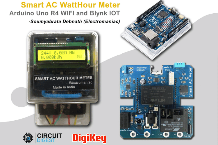
I decided to create a Smart AC watt-hour meter after experiencing a spike in my electricity bill that left me both shocked and curious. Each month, I tried to be mindful of my energy use, but I realized I had no clear way to track which appliances were consuming the most power or when. I also noticed that many homes and businesses around me faced similar challenges, unaware of their real-time energy usage, leading to unnecessary expenses and often wasting power.
With my interest in electronics and IoT, I knew I could build a solution to monitor power consumption accurately. I wanted to design a device that could give me real-time feedback on voltage, current, power, and even environmental conditions, like temperature and humidity, that might affect energy usage. I also wanted to be able to access this information remotely, so I integrated Wi-Fi, allowing data to be monitored and controlled via an online dashboard.
Adding safety features was crucial. I included a vibration sensor and magnet sensor to detect tampering, a flame sensor for fire alerts, and a relay to remotely shut off when needed. This project quickly turned into more than just a personal need; it became a tool I could offer to others to manage energy responsibly.
Creating this Smart AC watt-hour meter has been incredibly fulfilling. Not only am I reducing my own energy costs, but I'm also contributing to a sustainable approach to power usage—one smart meter at a time.
Components Required
| ID | Part Number | Name | Qty |
|---|---|---|---|
| 1 | CR2032-BS-6-1 | CR2032-BS-6-1 | 1 |
| 2 | VZT221M1CTR-0606ACS | 220uF | 1 |
| 3 | CC1206KKX7R0BB104 | 100nF | 5 |
| 4 | CC1206KKX7R0BB105 | 105 | 2 |
| 5 | CC1206KKX7ROBB102 | 102 | 2 |
| 6 | CC1206KKX7R0BB104 | 1nF | 1 |
| 7 | XKTF-N02-N | XKTF-N02-N | 1 |
| 8 | SM4007PL | SM4007 | 1 |
| 9 | HLK-5M05 | HLK-5M05 | 1 |
| 10 | DHT11 | DHT11 | 1 |
| 11 | X6511WV-19H-C60D30 | X6511WV-19H-C30D60 | 1 |
| 12 | X6511WV-08H-C60D30 | X6511WV-08H-C30D60 | 1 |
| 13 | X6511WV-10H-C60D30 | X6511WV-10H-C30D60 | 1 |
| 14 | ACS770LCB-050B-PFF-T | ACS770LCB-050B | 1 |
| 15 | SLC-05VDC-SL-A | SLC-05VDC | 1 |
| 16 | XH-5A | XH-5A | 1 |
| 17 | PD333-3B/L3 | PD333-3B/L3 | 1 |
| 18 | WS2812B-XF02/W | WS2812B | 1 |
| 19 | HDR-M-2.54 1x1 | HDR-M-2.54 1x1 | 4 |
| 20 | MMBT3904 | 3904 | 1 |
| 21 | RC1206JR-073K3L | 3.3kΩ | 4 |
| 22 | RC1206JR-074K7L | 4.7kΩ | 1 |
| 23 | RC1206JR-0710KL | 10kΩ | 12 |
| 24 | RC1206JR-07110KL | 1kΩ | 1 |
| 25 | 3296W-1-103 | 10kΩ | 3 |
| 26 | RC1206JR-07470RL | 470Ω | 1 |
| 27 | RC1206JR-07100RL | 100 | 1 |
| 28 | RC1206JR-07100KL | 100kΩ | 2 |
| 29 | DS3231SN# | DS3231 | 1 |
| 30 | LM393DR | LM393DR | 2 |
| 31 | SN74LVC125APWR | 74LVC125 | 1 |
| 32 | LM358DT | LM358DT | 1 |
| 33 | RN-1/2W-820KQ±2% T | 820kΩ | 1 |
| 34 | HX3144ESO | HX3144 | 1 |
| 35 | SW-18015PZR-10G12B2 | SW-18015PZR-10G12B2 | 1 |
| 36 | Arduino UNO R4 WIFI | Arduino UNO R4 WIFI | 1 |
| 37 | ZMPT107-1 | ZMPT107-1 | 1 |
Navigate to this YouTube Video for Full Demonstration of the Project
Reasons For Choosing Arduino Uno R4 WIFI For My Smart AC Meter Project
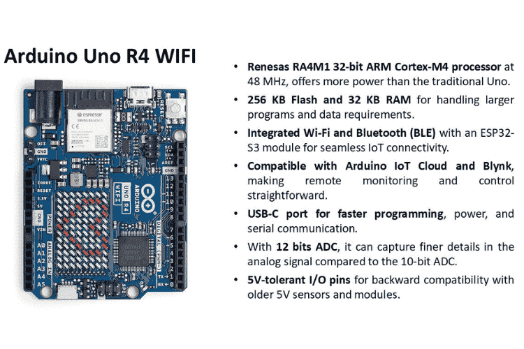
CircuitDigest gave 3 different MCU boards to choose from for building my project. I chose the Arduino Uno R4 WiFi for my Smart AC Meter project due to several key features that make it ideal for IoT and data-intensive applications like this.
Powerful Processor: It’s powered by the Renesas RA4M1 32-bit ARM Cortex-M4 running at 48 MHz. This provides significantly more processing power than traditional Arduino boards, which is essential for accurately calculating power, energy, and handling real-time data.
Large Memory: With 256 KB of Flash memory and 32 KB of RAM, I have enough storage and memory to handle larger programs and complex data processing tasks. This is particularly useful for data logging and any additional features I might want to add in the future.
IoT Capabilities: The integrated Wi-Fi and Bluetooth (BLE), powered by an ESP32S3 module, allows seamless wireless connectivity. This is crucial for my project since I need to send data to platforms like Blynk or Arduino IoT Cloud for remote monitoring and control.
12-bit ADC: The board’s 12-bit ADC (Analog-to-Digital Converter) allows it to capture analog signals with greater resolution. This means it can detect more subtle changes in the AC signal, leading to more accurate measurements, which is vital for power monitoring.
USB-C Port: The USB-C port provides faster programming and data communication. This is convenient for development and debugging as it saves time compared to older micro-USB or serial interfaces.
5V Compatibility: The 5V-tolerant I/O pins make this board compatible with older 5V sensors and modules, so I can integrate legacy components without issues.
Overall, these features provide the processing power, memory, connectivity, and compatibility I need to build a reliable and accurate Smart AC Meter with IoT capabilities. Also, I have a 15 Years of experience with Arduino environment which is an added benefit in this case.
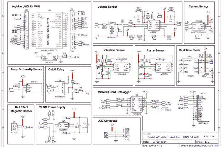
Circuit Diagram for The Customised Arduino Shield Expansion Board
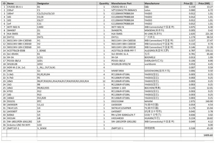
Complete Bill of Materials and Components Used
Designing the PCB of the Expansion Board
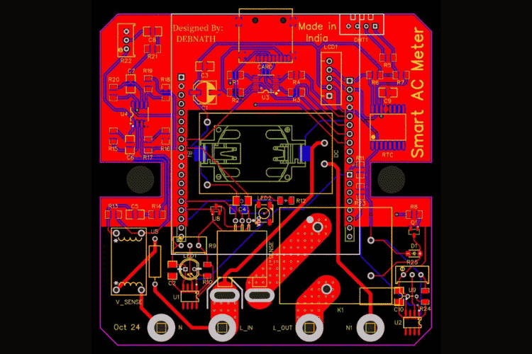
Different Components and Sensors Used in The Customised Arduino Shield Expansion Board
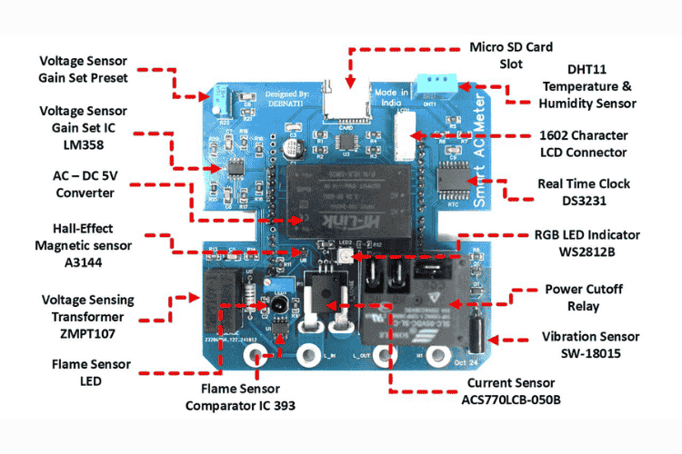
For my Smart AC Meter project, I chose a set of components that enhance the functionality, reliability, and safety of the device:
Voltage Sensor Gain Set Preset: This adjustable preset allows fine-tuning of the voltage sensor gain, ensuring accurate voltage measurements.
Voltage Sensor Gain Set IC (LM358): The LM358 operational amplifier is used to amplify the voltage signal, allowing for precise signal processing.
AC–DC 5V Converter: This converter transforms AC mains voltage into a stable 5V DC supply, powering the entire circuit safely and efficiently.
Hall-Effect Magnetic Sensor (A3144): This sensor detects magnetic fields, which can be useful for sensing magnetic interference or for anti-tampering applications within the meter.
Voltage Sensing Transformer (ZMPT107): The ZMPT107 transforms the AC mains voltage to a lower, measurable level, providing safe isolation and accuracy in voltage sensing.
Flame Sensor LED: This flame sensor detects a flame or fire hazards near the device.
Flame Sensor Comparator IC (393): The LM393 comparator processes the flame sensor signal, allowing for reliable flame detection in unsafe conditions.
Current Sensor (ACS770LCB-050B): This Hall-effect current sensor measures the AC current with high accuracy, essential for calculating power and energy consumption.
Vibration Sensor (SW-18015): This sensor detects vibrations, adding a layer of antitampering protection by automatically cutting power if abnormal shocks or knocks are sensed.
Power Cutoff Relay: The relay enables control of the power supply to the connected load, allowing automatic shutdowns in case of faults or non-payment of outstanding bills.
RGB LED Indicator (WS2812B): This RGB LED provides visual feedback on the meter’s status, such as normal operation, alerts, or errors, using different colours.
Real Time Clock (DS3231): The DS3231 RTC keeps precise time, allowing the meter to log power usage accurately over time for better energy tracking.
1602 Character LCD Connector: The connector enables easy interfacing with a 1602 LCD, displaying real-time data such as voltage, current, and power usage.
DHT11 Temperature & Humidity Sensor: This sensor monitors the ambient temperature and humidity, useful for assessing environmental conditions around the meter.
Micro SD Card Slot: The SD card allows for data logging and backup, making it easy to store and analyse power usage history directly from the meter.
Each of these components adds functionality or improves the overall reliability of the Smart AC Meter, making it a versatile and powerful tool for monitoring energy usage.
Blynk IOT Web Console and Dashboard
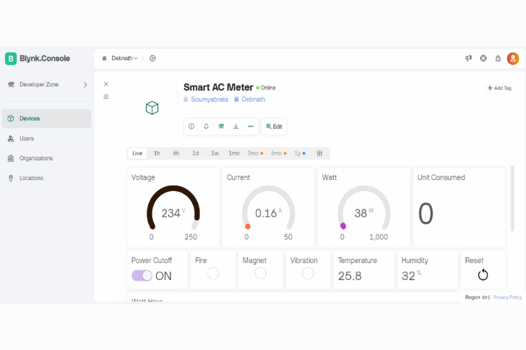
A Blynk console dashboard for the "Smart AC Meter," was created for the Power Supply Company. The dashboard is online and displays various real-time measurements and controls related to the smart meter:
Voltage: Shows a reading of 234V, with a gauge ranging from 0 to 250.
Current: Displays a reading of 0.16A, with a gauge ranging from 0 to 50.
Wattage: Indicates power consumption at 38W, with a gauge ranging from 0 to 1,000.
Unit Consumed: Displays the total energy consumed, currently at 0 units.
Power Cutoff: A switch control "Power Cutoff" is toggled to ON, it has the ability to remotely control power.
Sensors and Indicators: Fire, Magnet, and Vibration sensors are shown as small indicators, all currently off.
Temperature is displayed as 25.8°C, and humidity as 32%.
Reset: The button labelled as "Reset" is for resetting units consumed when it has maxed out.
The console includes a navigation menu on the left for accessing developer tools, devices, users, organizations, and locations. Tabs above the data allow time-based filtering for Live, 1h, 6h, 1d, and other options.
Code and Its Explanation
Smart AC Meter V1.0
Author - Soumyabrata Debnath (Electromaniac)
*/
#define BLYNK_TEMPLATE_ID "TMPL305u1Yyr5"
#define BLYNK_TEMPLATE_NAME "Arduino Uno R4 Wifi"
#define BLYNK_DEVICE_NAME "Smart AC Meter"
#define BLYNK_AUTH_TOKEN "SYti1igmTZh5q-98muVFqt2absT2VoMX"
//Libraries Initialization
//Wifi Specific
#include <WiFiS3.h>
#include <WiFiUdp.h>
#include <NTPClient.h>
#include <BlynkSimpleWifi.h>
//Pheripherials Specific
#include <SD.h>
#include <SPI.h>
#include <DHT.h>
#include <Wire.h>
#include <RTClib.h>
#include <EEPROM.h>
#include <ZMPT101B.h>
#include <Adafruit_NeoPixel.h>
#include <LiquidCrystal_I2C.h>
Blynk Template and Authentication
Token Declaration: The Blynk template and authentication token are initialized at the beginning to enable secure cloud-based control and monitoring through the Blynk dashboard.
Required Libraries Declaration: All necessary libraries are included, such as for sensors, WiFi, SD card, Blynk, EEPROM, and other essential modules, ensuring the functionality of various components and data handling.
//Pin Mappings
#define NC 0 //Rx
#define NC 1 //Tx
#define vbSense 2
#define relayPin 3
#define NC 4
#define NC 5
#define NC 6
#define fSense 7
#define NC 8
#define tSense 9
#define chipSelect 10
#define MOSI 11
#define MISO 12
#define SCK 13
#define vSense 14
#define iSense 15
#define mSense 16
#define aLED 17
#define NC 18 //SDA
#define NC 19 //SCL
char auth[] = BLYNK_AUTH_TOKEN;
char ssid[] = "Russo"; // WiFi SSID
char pass[] = "0123456789"; // WiFi password
Defining Pins Connected to Sensors and Components: The pins for each sensor and component (like voltage, current, vibration sensors, relay, etc.) are assigned, allowing the microcontroller to interact with the external devices correctly.
//Peripherals Initialization
RTC_DS3231 rtc;
WiFiUDP ntpUDP;
BlynkTimer timer;
DHT dht(tSense, DHT11);
ZMPT101B voltageSensor(vSense, 50.0);
LiquidCrystal_I2C lcd(0x27,16,2); // lcd(address,column,row)
Adafruit_NeoPixel strip = Adafruit_NeoPixel(1, aLED, NEO_GRB + NEO_KHZ800);
NTPClient timeClient(ntpUDP, "pool.ntp.org", 19800, 60000); // India Timezone (GMT+5:30)
Peripherals Initialization: Initialization of peripherals, such as the LCD display and sensors, is done to set them up for communication and proper operation.
/ Variables Declaration
bool relayFlag = false;
float voltageRMS = 0.0;
float currentRMS = 0.0;
float watt = 0.0;
float eConsumed = 0.0; // Total energy consumed in kWh
int unitCount = 0; // To track 1 kWh units
bool data_saved = false; // Flag to ensure data is saved once at 9 AM
int mState = HIGH; // Variable to store Hall sensor state
int vbState = HIGH; // Variable to store Vibration sensor state
int fState = HIGH; // Variable to store Flame sensor state
int mStateFlag = 0; // Variable to store Hall sensor state
int vbStateFlag = 0; // Variable to store Vibration sensor state
int fStateFlag = 0; // Variable to store Flame sensor state
int ledState = LOW; // LED on/off state
const int unitAddr = 0; // EEPROM address to store unit count
unsigned long lastTime = 0;
unsigned long CprevMillis = 0; // Store the last time the function ran
Variables Declaration: Variables are declared to store data like voltage, current, power, and sensor readings, which will be used across different functions for calculations and data logging.
void send_vSense() {
voltageRMS = voltageSensor.getRmsVoltage(100);
Blynk.virtualWrite(V0, voltageRMS); // S
}
Blynk Send Volt Function: This function reads the voltage data from the voltage sensor and sends it to the Blynk dashboard for real-time monitoring.
void send_iSense() {
float isumOfSquares = 0.0;
for(int i = 0; i < 1000; i++) {
int isensorValue = analogRead(iSense); // Read sensor value
float iVoltage = (isensorValue * 5000.0) / 4096.0;// Convert ADC value to voltage
float current = (iVoltage - 2500) / 45.0; // Convert voltage to current
isumOfSquares += current * current; // Square each current value and sum them up
}
float imeanOfSquares = isumOfSquares / 1000; /
currentRMS = sqrt(imeanOfSquares);
if (currentRMS <= 0.1) {
currentRMS = 0;
}
Blynk.virtualWrite(V1, currentRMS);
}
Blynk Send Current Function: This function reads the current from the current sensor (ACS770) and sends it to the Blynk dashboard, displaying real-time current usage.
void send_watt() {
watt = voltageRMS * currentRMS;
} Blynk.virtualWrite(V2, watt); // Send watt to Blynk (Virtual Pin V2)
void send_unit() {
Serial.println(unitCount);
} Blynk.virtualWrite(V3, unitCount); // Send unit to Blynk (Virtual Pin V3)
void send_tSense() {
float t = dht.readTemperature() - 10; // Read temperature in Celsius
float h = dht.readHumidity(); // Read the humidity
Serial.println(t); // Print temperature to serial monitor
Serial.println(h); // Print humidity to serial monitor
Blynk.virtualWrite(V4, t);
// Send temperature to Blynk (Virtual Pin V4)
Blynk.virtualWrite(V5, h); // Send humidity to Blynk (Virtual Pin V5)
}
void send_mSense() {
mState = digitalRead(mSense); // Read hall sensor state
if (mState == LOW) { // If a magnet is detected (hall sensor output LOW)
digitalWrite(relayPin, LOW); // Turn relay OFF
Serial.println("Magnet detected: Relay OFF");
mStateFlag = 1;
relayFlag = false;
Blynk.virtualWrite(V9, relayFlag);
}
Serial.print("mState:");
Serial.println(mState); // Print hallState to serial monitor
Blynk.virtualWrite(V6, mStateFlag); // Send hallState to Blynk
}
void send_vbSense() {
vbState = digitalRead(vbSense); // Read vibration sensor state
if (vbState == LOW) { // If a vibration is detected (vibration sensor output LOW)
digitalWrite(relayPin, LOW); // Turn relay OFF Serial.println("Vibration detected: Relay OFF");
vbStateFlag = 1;
relayFlag = false;
Blynk.virtualWrite(V9, relayFlag);
}
Serial.print("vbState:");
Serial.println(vbState); // Print vbState to serial monitor
Blynk.virtualWrite(V7, vbStateFlag); // Send vbState to Blynk
}
void send_fSense() {
fState = digitalRead(fSense);
if (fState == LOW) { // Assuming LOW indicates flame detection
fStateFlag = 1; digitalWrite(relayPin, LOW); // Turn off relay Serial.println("Flame detected! Relay turned off.");
relayFlag = false;
Blynk.virtualWrite(V9, relayFlag);
Blynk Send Watt Function: This function calculates power in watts by multiplying the voltage and current values, then sends the power data to Blynk for monitoring.
Blynk Send Unit Function: The energy usage in kWh (units) is sent to Blynk, allowing the power supply company to monitor total energy consumption in units.
Blynk Send DHT11 Function: This function reads temperature and humidity data from the DHT11 sensor and sends it to the Blynk dashboard, providing environmental monitoring.
Blynk Send Hall Effect Sensor Function: The hall-effect sensor detects magnetic interference, which is monitored by sending data to the Blynk dashboard to ensure safe operation.
Blynk Send Vibration Sensor Function: The vibration sensor function checks for any unusual vibration (e.g., from tampering or environmental factors) and sends an alert to the Blynk dashboard.
Blynk Send Flame Detection Function: If the flame sensor detects any fire hazard, this function alerts the power supply company via the Blynk dashboard, enhancing safety.
}
Serial.print("Flame State:");
Serial.println(fState); // Print fState to serial monitor
Blynk.virtualWrite(V8, fStateFlag); // Send fState to Blynk
}
BLYNK_WRITE(V9) {
relayFlag = param.asInt(); // Update flag based on switch value from the dashboard
Serial.print("Relay state changed from Blynk: ");
Serial.println(relayFlag);
if (relayFlag) {
digitalWrite(relayPin, HIGH); // Turn relay ON
mStateFlag = 0;
vbStateFlag = 0;
fStateFlag = 0;
}
else {
digitalWrite(relayPin, LOW); // Turn relay ON
}
}
BLYNK_WRITE(V10) {
int buttonState = param.asInt();
if (buttonState == 1) { // Button pressed
unitCount = 0; // Reset unit count
writeUnitCount(unitCount); // Update EEPROM
Blynk.virtualWrite(V3, unitCount); // Update unit count on Blynk display
Serial.println("Unit count reset to 0");
}
}
void time_update() {
timeClient.update(); // Update NTP time
unsigned long epochTime = timeClient.getEpochTime(); // Get current time from NTP
DateTime currentTime = DateTime(epochTime); // Convert epoch time to DateTime object
rtc.adjust(currentTime); // Set time on DS3231
Serial.println("Time updated from NTP.");
}
void saveDataToCSV() {
File dataFile = SD.open("units.csv", FILE_WRITE); // Open the file
if (dataFile) {
DateTime now = rtc.now();
dataFile.print(now.year(), DEC);
dataFile.print('/');
dataFile.print(now.month(), DEC);
dataFile.print('/');
dataFile.print(now.day(), DEC);
dataFile.print(",");
dataFile.println(unitCount);
dataFile.close(); // Close the file
Serial.println("Data saved to SD card as CSV.");
}
Blynk Power Cutoff Relay Function: This function allows remote control of the relay through the Blynk dashboard, enabling power supply company to cut off power if needed, and includes two[1]way communication to update the relay state on both sides.
Blynk Power Unit Reset Function: This function enables resetting the power usage (units) counter to zero through the Blynk dashboard, useful for monthly resets or monitoring periods.
NTP Time Update Function: The NTP (Network Time Protocol) function updates the current time from the internet, ensuring accurate time stamped data for logging purposes.
SD Card Data Save Function: This function saves relevant data (such as voltage, current, power, and time) to the SD card, creating a record of power usage over time.
else {
Serial.println("Error opening file.");
}
}
void setLEDColor(int red, int green, int blue) {
strip.setPixelColor(0, strip.Color(red, green, blue)); // Set color of first LED
strip.show(); // Update LED strip
}
void writeUnitCount(int count) {
byte lowByte = count & 0xFF; // Lower 8 bits
byte highByte = (count >> 8) & 0xFF; // Upper 8 bits
EEPROM.write(unitAddr, lowByte); // Write lower byte to EEPROM
EEPROM.write(unitAddr + 1, highByte); // Write upper byte to next address
}
int readUnitCount() {
byte lowByte = EEPROM.read(unitAddr); // Read lower byte from EEPROM
byte highByte = EEPROM.read(unitAddr + 1); // Read upper byte from EEPROM
return (highByte << 8) | lowByte; // Combine the two bytes
}
void setup() {
Serial.begin(9600);
pinMode(iSense, INPUT);
pinMode(fSense, INPUT);
pinMode(vbSense,INPUT);
pinMode(mSense, INPUT_PULLUP);
pinMode(relayPin, OUTPUT); // Set relay pin as output
lcd.init();
lcd.home();
lcd.backlight();
Wire.begin();
rtc.begin();
analogReadResolution(12);
voltageSensor.setSensitivity(500.0);
Blynk.begin(auth, ssid, pass); // Connect to Blynk
dht.begin(); // Initialize DHT sensor
Blynk.syncVirtual(V9);
timer.setInterval(1000L, send_vSense); // Send voltage data every 1 seconds
timer.setInterval(1000L, send_iSense); // Send current data every 1 seconds
timer.setInterval(1000L, send_watt); // Send Watt data every 1 seconds
timer.setInterval(1000L, send_unit); // Send Unit counted every 1 seconds
timer.setInterval(1000L, send_tSense); // Send T/H data every 1 seconds
timer.setInterval(1000L, send_mSense); // Send Magnet data every 1 seconds
timer.setInterval(1000L, send_vbSense); // Send Vibration every 1 seconds
timer.setInterval(1000L, send_fSense); // Send Flame data every 1 seconds
unitCount = readUnitCount(); // Retrieve last saved unit count from EEPROM
Serial.print("Restored Unit Count: ");
Serial.println(unitCount);
timeClient.begin();
time_update();
File dataFile = SD.open("units.csv", FILE_WRITE);
if (dataFile) {
RGB Colour Settings Function: This function sets the RGB LED colour based on different operating states, such as normal, alert, or error, providing a visual indicator of the system's status.
EEPROM Power Unit Read/Write Function: The EEPROM function reads and writes power usage data to memory, ensuring that unit data persists across power cycles and resets.
Main Setup: The setup() function initializes all the components, connects to WiFi and Blynk, starts serial communication, and sets up timers and sensors, preparing the system for operation.
dataFile.println("Date,Units Consumed"); // Add a header row
dataFile.close();
}
strip.begin(); // Initialize the strip
strip.show(); // Initialize all pixels to 'off'
setLEDColor(0, 0, 10);
delay(2000); // Keep it on for 2 seconds
setLEDColor(0, 0, 0);
}
void loop() {
Blynk.run(); // Run Blynk
timer.run(); // Run timer
int state = digitalRead(relayPin);
if (state == LOW){
setLEDColor(20, 0, 0);
}
unsigned long currentTime = millis();
if (currentTime - lastTime >= 1000) {
lastTime = currentTime;
float power = voltageRMS * currentRMS; // Instantaneous power in watts
float energy = (power / 1000.0) / 3600.0; // Convert power to kWh over 1 second
eConsumed += energy; // Accumulate energy consumed
if (eConsumed >= 1.0) // Check if 1 unit has been consumed
{
unitCount += 1; // Increment 1 unit
eConsumed -= 1.0; // Reset energy consumption by 1 kWh
writeUnitCount(unitCount); // Store updated count in EEPROM
Serial.print("1 Unit Consumed. Total Units: ");
Serial.println(unitCount);
}
Serial.print("Voltage: ");
Serial.print(voltageRMS);
Serial.print("V, Current: ");
Serial.print(currentRMS);
Serial.print("A, Power: ");
Serial.print(power);
Serial.print("W, Energy: ");
Serial.print(eConsumed);
Serial.println(" kWh");
lcd.init();
lcd.clear();
lcd.setCursor(0, 0);
lcd.print(voltageRMS,0);
lcd.print("V");
lcd.setCursor(5, 0);
lcd.print(currentRMS,2);
lcd.print("A");
lcd.setCursor(11, 0);
lcd.print(power,0);
lcd.print("W");
lcd.setCursor(0, 1);
if (state == LOW){
lcd.print("Cuttoff");
}
Power Calculation in kWh and Units Consumed: Calculates the power in kilowatt-hours and updates the total units consumed, storing this data for usage tracking.
LCD Display Print: Displays the current voltage, current, power, and units consumed on the LCD, providing an easy-to-read interface.
else{
lcd.print(eConsumed,3);
lcd.print("kWh");
}
int unitPosition = 15 - String(unitCount).length();
lcd.setCursor(unitPosition, 1);
lcd.print(unitCount);
lcd.print("U");
}
unsigned long currentMillis = millis();
static unsigned long previousMillis = 0;
static unsigned long ledOnMillis = 0;
static bool ledState = LOW;
if (watt > 0){
int flashDelay = map(watt, 0, 5000, 2000, 100);
if (currentMillis - previousMillis >= flashDelay) {
previousMillis = currentMillis;
if (ledState == LOW) {
setLEDColor(0, 20, 0); // Set LED to red
ledState = HIGH;
ledOnMillis = currentMillis; // Record the time LED turned on
}
}
if (ledState == HIGH && (currentMillis - ledOnMillis >= 100)) {
setLEDColor(0, 0, 0); // Turn off LED
ledState = LOW;
}
}
if (watt <= 0 && state == HIGH){
setLEDColor(0, 0, 0);
}
if (currentMillis - CprevMillis >= 60000) {
CprevMillis = currentMillis; // Save the last time the function was called
time_update(); // Run the time update function
}
DateTime now = rtc.now(); // Get current time from RTC
if (now.hour() == 9 && now.minute() == 0 && now.second() == 0 && !data_saved) {
saveDataToCSV(); // Save data to SD card
data_saved = true; // Ensure data is saved only once at 9am
}
if (now.hour() != 9) {
data_saved = false;
}
}
RGB Blink Frequency Function According to Watts Consumed: Adjusts the RGB LED blinking frequency based on power consumption, offering visual feedback on energy usage.
Time Update and SD Card Save Schedule: Periodically updates the time using NTP and saves the collected data to the SD card, ensuring accurate data logging and tracking.
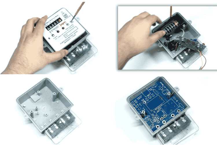
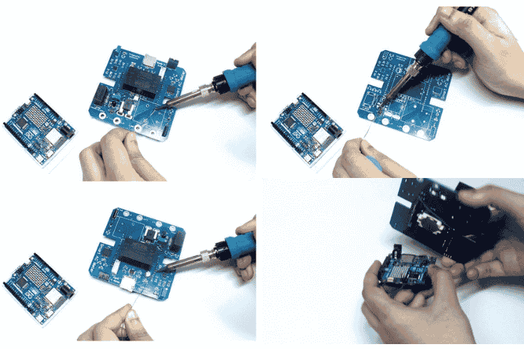
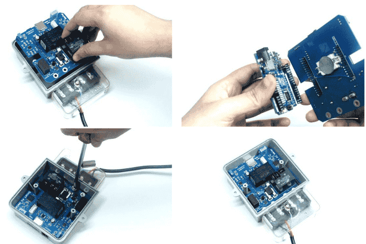
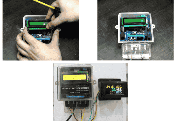
Some Pictures from Construction Of The Project
Working Demonstration and Results
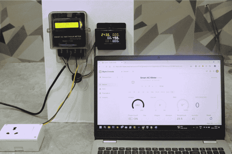
I have thoroughly demonstrated the working of the Smart AC meter in my attached video. Kindly watch the video to have a clear idea about how it works and functions.
Click on the GitHub Image to View or Download Code


