

We have been using Raspberry Pi for a long time to create many exciting projects. But, oftentimes we face an issue in selecting the best power source for our projects, and sometimes when the power goes off, our raspberry pi turns off abruptly which might corrupt the OS or in the worst-case damage the board itself. So, today we are building our own Raspberry Pi Zero HAT that can be mounted directly on top of a pi zero board (or any other Pi Board). This Raspberry UPS HAT will have a TP4056 based single 18650 battery charger, a 18650 single cell holder, and an MT3608 based booster on it. The MT3608 will boost up the input voltage to 5V to power up the Pi.
This whole HAT is made into a compact small PCB board which was fabricated by 7pcb.com (also known as Bittele) and because of its small size we can easily carry it around along with our Raspberry Pi. 7PCB is a complete turn-key PCB solution provider who has their Production Facility both in China and as well as Canada. They can handle PCB fabrication, Parts Procurement, and also PCB Assembly even for low and mid volumes, we will discuss more on that later.
Apart from just acting as a power source for Pi, our Raspberry HAT also has some additional power outlets like a USB output port and a few more 5V and 3.3V pins that can be used to power others sensors and modules and we might want to use with our raspberry pi. So in this project, we will show you how to design your own Battery HAT for Raspberry Pi and also show you how to fabricate it using 7pcb.com, so let's get started.
Giveaway Alert !!
We are giving away three of these Raspberry pi Power HAT PCBs with all the components and a few more goodies to our audience. Check out our Giveaway Page to participate.
You can watch the complete overview of this Raspberry Pi HAT, also you will get to know about Giveaway.
Components Required for Making Pi HAT
- TP4056 Module
- USB Female Jack
- 18650 Li-Ion Battery Holder
- 18650 Li-ion Cell
- SMD Components (As per the Schematic)
Note: I am attaching the BOM along with this article, you can download and see the SMD and THT components required for the PCB.
Power Consumption of Raspberry Pi
Since calculation and estimation of power consumption for the project is a necessary task for an engineer, we must know the idle power consumption of an individual Raspberry Pi. I’ve listed out some of the most commonly used cases here:
|
Component |
Power Consumption (on 5V) |
|
Raspberry Pi zero 2W HDMI off, LED off |
100 mA (0.6 Watt) |
|
HDMI off, LED off, onboard WiFi on |
120 mA (0.7 W) |
|
Raspberry Pi zero HDMI off, LED off, Wifi on |
120 mA (0.7 Watt) |
|
Raspberry Pi 2 B idle |
220 mA (1.1 Watt) |
|
Ab -n 100 -c 10 (uncached) |
450 mA (approx 2.3 Watt) |
|
400% CPU Load |
400 mA (approx 2.1 Watt) |
|
Raspberry Pi 3 B idle |
260 mA (1.4 Watt) |
|
Ab -n 100 -c 10 (uncached) |
480 mA (2.4 Watt) |
|
400% CPU Load |
730 mA (3.7 Watt) |
|
Raspberry Pi 3 B+ idle |
350 mA (1.9 Watt) |
|
Ab -n 100 -c 10 (uncashed) |
950 mA (5.0 Watt) |
|
400% CPU load |
980 mA (5.0 Watt) |
|
Raspberry Pi 4 B idle |
540 mA (2.7 Watt) |
|
Ab -n 100 -c 10 (uncached) |
1010 mA (5.1 Watt) |
|
400% CPU load |
1280 mA (6.4 Watt) |
Note: We have not included the power taken by Mouse and Keyboard or any other peripherals as they will consume the power accordingly and can be added to the above-stated power.
Raspberry Pi HAT Circuit Diagram

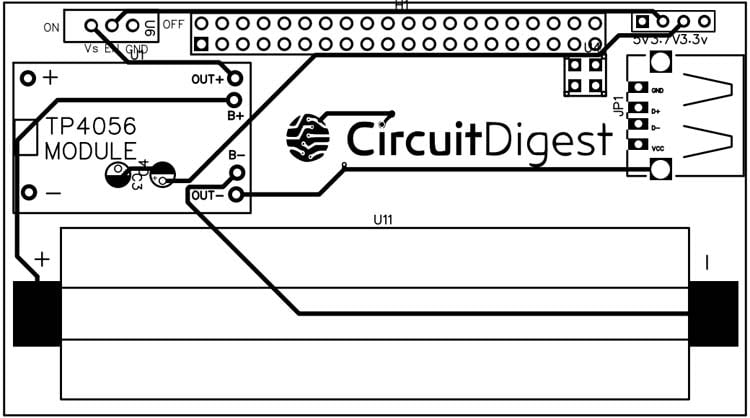
Here you can see that there is a TP4056 Module that will charge our 18650 cell, and is attached with the slide switch. The long male header is there for mounting the Raspberry pi with the help of its GPIOs. Now in the middle of the schematic, there is an MT3608 IC that will boost up the power supply from 3.3V to 5V for the Raspberry Pi. MT3608 is a DC-DC boost converter that can give output up to 2A. More specifically it supports a wide range of input voltage i.e. from 2V to 24V DC and can give output from 5V to 28V. A boost converter is used to step up a lower voltage to a higher voltage. It is a type of switch-mode power supply as it uses a switching device for regulating the voltage. In our case, MT3608 IC is the switching module, which has a high switching frequency of 1.2MHz.
Whenever current is passed through an inductor (L1) it induces some magnetic field. Now when we change the current level passing through it, the magnetic field collapses to generate a high voltage spike. Having a high switching frequency IC (MT3608) allows this principle to happen by generating and collapsing the magnetic field induced by the inductor. When the switching module is off, the voltage spike passes through the Schottky diode (D1) and gets stored in the capacitor(C2) hence increasing the voltage of the capacitor and we obtain a higher voltage level output across the capacitor. The Schottky diode (D1) plays an important role in blocking a reverse current to the circuit.
Now the output voltage of the booster can be set by calculating the right pair of resistors, here we require approximately 5.2V to power up the raspberry. So, the relation will be

Where Vref = 0.6
And Vout is 5.2V
So, I have taken up the combination of 1.2K Ohm and 150 Ohm resistors as R1 and R2 respectively that is giving me almost 5.2V.
Circuit and PCB Layout
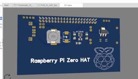
So, this is the PCB Layout Image for your Reference. I am attaching a 3D view of the PCB I made too. I am attaching the complete gerber file of the PCB here, you can easily download it and proceed with ordering your PCBs on 7pcb.com by following the steps below.
Ordering PCBs from 7PCB
Getting your PCBs fabricated from 7PCB (a.k.a Bittele) is very simple, all you have to do is follow these 4 simple steps.
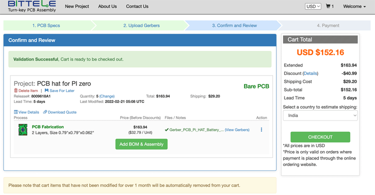
Step 1: Open any browser of your choice and get into their website 7PCB.com, which will take you to their home page. There just click on “Instant Online Quote and Order” and you will see the following page.
If you are using 7pcb for the first time make sure you have already registered for an account. I already have an account and it is logged in already.
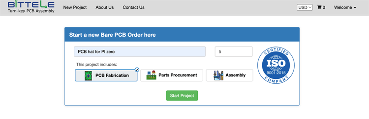
Step 2: Bittele offers complete turn-key solutions, meaning they can not only fabricate your PCB boards but can also find the right parts for your board and even assemble them for you. For now, I am just going to order the boards, so I only clicked on “PCB Fabrication” and disabled the other two. Then Entered a project Name and required quantity and click on “Start Project” which opened the below page
Here you can enter the size of your PCB and other required parameters, I left most of them to the default values. On the right side, you can see the total cost for your PCBs to be fabricated, after checking the cost you can click on “Save and Continue”.

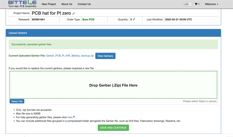
Step 3: On the next page, you can upload the Gerber file for your project. I have attached the Raspberry Pi Battery HAT PCB Gerber file as you can see in the below image. After uploading the file, click on Save and Continue.
Step 4: The last step is to enter your shipping details and proceed with payment. Just select the county to which your PCB has to be shipped, in my case, it is “India”. After confirming the final price you can click on “Checkout” and proceed with entering your shipping details and making the payment.
Once you have done that, Bittele will start fabricating your PCB boards and ship them directly to your doorstep.
PCB Quality from 7PCB
Within a couple of weeks from ordering my PCBs, I got them delivered to my address in a neatly packaged box. You can see both the front side and backside of the PCBs in the below image.
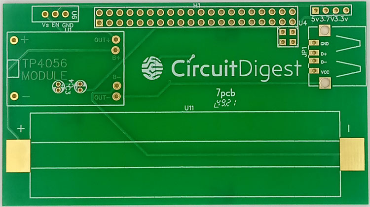
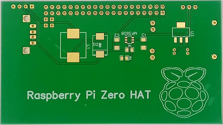
As you can see the quality of the PCBs is very professional and I had no trouble using them. All the vias were neatly drilled in the exact same size and the quality of the pads was also good. If you want to get your hands on these PCBs for free you can check out our Giveaway Page and take part in it.
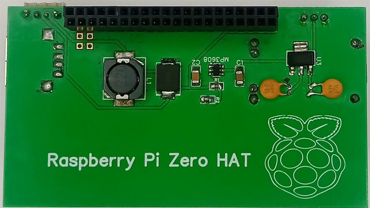
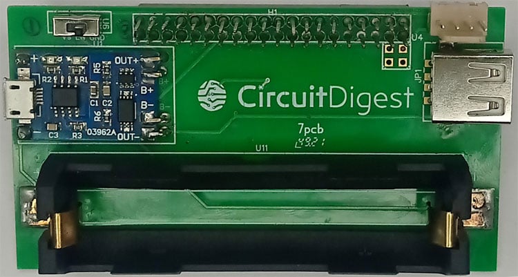
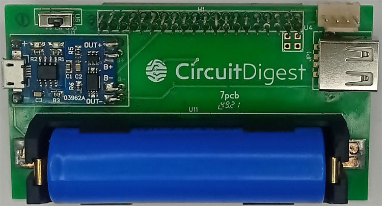
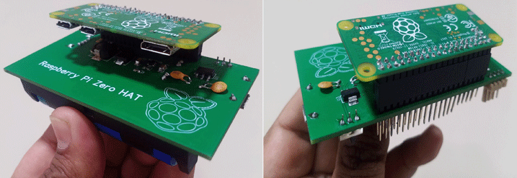
Raspberry Pi Battery HAT - Assembled
The below images shows the Raspberry Pi Power HAT after it is assembled. Here you will see that the battery 18650 is plugged into the holder and all the components are soldered. You can also see how the board is mounted to a Raspberry Pi Zero.
Testing our Pi Zero Battery HAT
Now that we have built our Li-ion Battery Hat for Raspberry Pi, it is time to test it. To demonstrate that everything is working fine we have connected the RPI UPS HAT to Raspberry Pi and have also used its USB port to power a 7 inch HDI screen.
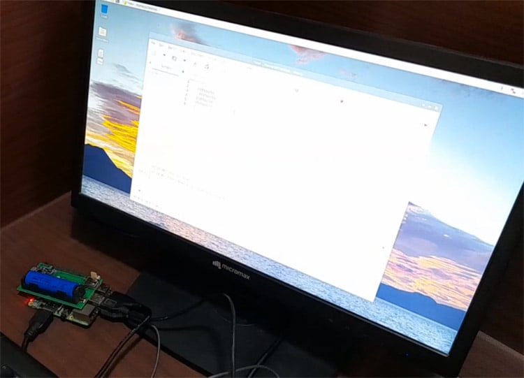
As you can see in the above image the Pi Battery Hat was not only able to power and boot the Raspberry Pi board but also power the LCD screen. Now how long will it be able to power depends on what other peripherals are connected to the Pi and how much computational power is used. You can also check the complete working in the video given below.
Conclusion
Hence, we have successfully made and tested our customized Pi HAT for various versions of Raspberry Pi. This printed circuit board will be very useful when you want to make projects that require a low-powered independent setup. And it can work for many other applications as well. Please feel free to share your ideas with us, also. If you have any queries then please ask in the comment section or forum.

Great article. I am planning to adopt your work for a project. Could you please share what are the sizes of the capacitor, inductor, and resistor smd? Thanks!