

Raspberry Pi-based systems require internet connectivity to work at full potential, this is especially true for applications like IoT, image processing, remote sensing, and other cloud-based applications. Consider the case below: You need humidity sensor data in an agricultural field 200 meters away from your control unit, but there is no internet access or a power outlet in the field. Because of the lack of power outlets in those remote regions, long-distance deployment is now hampered.
What if we can use a single LAN cable to provide both power and data to our raspberry pi? This scenario, in which Internet and power are both delivered over the same LAN wire is known as Power Over Ethernet and in this tutorial, we will be learning exactly about that. We will discuss What is PoE? and how to use PoE with Raspberry Pi. Using the Perf Board, we'll make our own POE Hardware Attachment (HAT) for the Raspberry Pi and a POE Injector today. So let's begin!!

Components Required to build a PoE HAT for Raspberry Pi
- RJ45 Female Socket (Ethernet Female socket) x 2
- Female DC Jack x 2
- Perf Board
- 2596 Buck Converter Module x 1
- DC Fan for Pi x 1
- USB Female Jack x 1
- Standoff for pi x 2
- USB Cable for powering pi
What is PoE and How is it useful?
PoE or Power Over Ethernet is a technology that allows you to transport power and data over a long distance using an ethernet cable.
In terms of internet connectivity, wireless connections such as Wifi, WLAN, WiMaX, and mobile networks are becoming more common these days, yet wired networks retain their relevance since data transfer speeds cannot be matched by wireless networks. As a result, we continue to believe that wired LAN-based networks have their own value and are thus commonly selected.
Power over Ethernet (PoE) is an acronym for power over Ethernet. This technique enables data and power to be sent via a single CAT5e ethernet connection. This technology is used in IP phones, security cameras, and wireless access points, to name a few.
Since Ethernet connections are considered to be the greatest quick and reliable method for data transfer, there was one thing that was still trailing behind: the transfer of electricity. Because all technological gadgets require power to operate. In the below table you can see the various PoE Power capacity standards that are being followed till date.
IEEE Extension | Type | Power Capacity |
IEEE802.3af | Type 1 | 15.4Watt |
IEEE802.3at/PoE+ | Type 2 | 30.8Watt |
IEEE802.3bt/UPoE | Type 3 | 60Watt |
IEEE802.3bt | Type 4 | 90Watt |
Advantages of POE
- You may save time and money by using PoE to install new power lines.
- Network cables do not require the services of a licensed electrician to install, and they may be placed almost anywhere.
- PoE installation is also far less expensive than regular wiring.
- PoE allows you to mount devices in awkward or distant areas where installing electricity would be difficult.
- Furthermore, PoE may be transferred and disconnected with ease. It's similar to plug-and-play, in that you don't have to destroy the entire network to move it around.
- If you want to deploy wireless access points or Pi with cameras, PoE is ideal.
Types of Power over Ethernet
Generally, there are two types of PoE, one is Active and another is Passive.
Active PoE: To put it simply, Active PoE is any sort of PoE that negotiates the proper voltage between the switch and the PoE-powered device. Whereas Passive PoE doesn't negotiate, thus it always sends a set voltage of electric current out across the Ethernet line, regardless of the device it's going to.
Passive PoE: Often known as passive Power Over Ethernet, is a non-standard PoE. It can also supply electricity via Ethernet cables without requiring any kind of negotiation or contact. There is no IEEE standard for a passive PoE switch.
So, in order to make things easier, we'll try to construct a Passive POE for our Raspberry Pi. But before going further let’s see the power consumption of a raspberry pi so that we will know how much power should be transferred via our Ethernet cable.
Power Consumption of Raspberry Pi
Since calculation and estimation of power consumption for the project is a necessary task for an engineer, we must know the idle power consumption of an individual Raspberry Pi. I’ve listed out some of the most commonly used cases here:
Component | Power Consumption (on 5V) |
Raspberry Pi zero 2W HDMI off, LED off | 100 mA (0.6 Watt) |
HDMI off, LED off, onboard WiFi on | 120 mA (0.7 W) |
Raspberry Pi zero HDMI off, LED off, Wifi on | 120 mA (0.7 Watt) |
Raspberry Pi 2 B idle | 220 mA (1.1 Watt) |
Ab -n 100 -c 10 (uncached) | 450 mA (approx 2.3 Watt) |
400% CPU Load | 400 mA (approx 2.1 Watt) |
Raspberry Pi 3 B idle | 260 mA (1.4 Watt) |
Ab -n 100 -c 10 (uncached) | 480 mA (2.4 Watt) |
400% CPU Load | 730 mA (3.7 Watt) |
Raspberry Pi 3 B+ idle | 350 mA (1.9 Watt) |
Ab -n 100 -c 10 (uncashed) | 950 mA (5.0 Watt) |
400% CPU load | 980 mA (5.0 Watt) |
Raspberry Pi 4 B idle | 540 mA (2.7 Watt) |
Ab -n 100 -c 10 (uncached) | 1010 mA (5.1 Watt) |
400% CPU load | 1280 mA (6.4 Watt) |
Note: We have not included the power taken by Mouse and Keyboard or any other peripherals as they will consume the power accordingly and can be added to the above-stated power.
Ethernet Cable Pinout
Since we are working with LAN cables for PoE, it is important to know about the functionalities of the different wire pairs that we will find inside an Ethernet cable. The below image shows the Ethernet cable pinout that is currently available on the market.
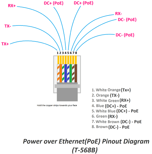
PoE switches may deliver power in three ways: PoE Mode A, PoE Mode B, and 4-pair PoE. Power and data are transmitted concurrently across pins 1, 2, 3, and 6 in PoE Mode A. Power is pumped onto pins 4, 5, 7, and 8 in PoE Mode B. In addition, 4-pair PoE distributes power to all 8 pins at the same time. PoE Mode A, PoE Mode B, and 4-pair PoE are all supported by active PoE switches, but passive PoE switches only support PoE Mode B.
We are making PoE ModeB for our Raspberry Pi 3B+, the below image shows the PoE pins on Raspberry Pi.

Building a POE Injector for Raspberry Pi
A PoE injector, in particular, may be used to connect a network switch to a wireless access point, IP phone, network camera, or any other IEEE 802.3af/at-powered device (PD). A PoE-enabled network device is connected to a non-PoE LAN switch port with a PoE injector.
Basically, PoE injector has 2 inputs, one is for DC power and the other is Ethernet port. We will be making our own passive PoE injector that will inject or add a potential difference of DC 12V in the LAN cable using a 12V power adaptor. Now let's talk about the connections.

Because the connections are straightforward, we must determine which pair of wires is available for power transmission and which pair is responsible for data.
Here in the above image, you can see that pair 4-5 and pair 7-8 are responsible for the power transmission and the remaining 1-2 and 3-6 are for data transmission. So now let’s look at the circuit, we have used to build our PoE injector.

We have used pin 4 and 5 to carry power and pin 7 and 8 as ground. The remaining pins are used to carry data. I have just used two Ethernet connectors and one DC jack to build my bare minimum PoE injector on a zero PCB. You can see the completed board below.

Why do PoE’s work on 12V or more?
Now we all know that your Pi only needs 5V to power up, but why do we provide 12V over the Ethernet cable? The answer is power loss and low current requirements. When we are sending power through wires for a long distance there will be a power loss and as a result, there will be a voltage drop within the cable. Hence despite providing 12V on the inject we will get only around 10-11V on the receiving side based on the length of the cable.
Another reason is we should keep the current through these LAN cables as minimum as possible. According to ohms law, the higher the voltage the lower will be the current for the same level of power. So PoE’s always work on higher voltage, there are certain PoE standards that even work as high as 57V.
Building a POE Splitter for Raspberry Pi
There are two input ports and one output port on this gadget. The input accepts a PoE Ethernet connection, while the output ports supply standard Ethernet and DC power. On the input side, there's PoE Ethernet.
On the output, we have a standard Ethernet connector as well as a DC power supply. The role of a PoE splitter is to separate a PoE Ethernet connection into standard Ethernet and usable DC power supply, which is the polar opposite of a PoE injector. Now we will see the circuit diagram of the POE Separator.

The circuit is very simple, we just have to use the PoE pin on Raspberry pi to obtain the 12V from the Ethernet cable. This 12V is then provided to an LM2596 buck converter to step it down to 5V which is then provided to the Raspberry Pi itself. We have also used this 12V to power a fan that will cool down the raspberry pi as it works. Now, for some reason, the Pi becomes comparatively hot power with PoE and it requires a cooling fan for safe operation. We are not aware of the reasons for this slight rise in temperature, if you know why Raspberry Pi gets hot on PoE do leave them in the comment section below.
Just like the PoE inject, we also built the PoE Hat on zero PCB as you can see below.

The boards are something like this when mounted on top of the Raspberry pi.

Once both the PoE injector and the PoE HAT are ready you can directly power them up, boot your Raspberry Pi, and check your internet connection. You can check out the working of both the boards in the video linked at the bottom of this page.
