
In our daily life we see vehicles turning indicators when they turn left or right. It looks like Simple LED Blinking. But it's not only simple blinking LEDs inside indicators of vehicles. Here we are building a fancy Car/Bike Turning Indicator Circuit using 555 Timer IC, with four LEDs glowing one by one in a particular pattern and we can control the speed or frequency of this LED indicator by simply turning a Potentiometer.
Components Required:
- BC547 or MPS A42 NPN transistor -4
- Bread Board -1
- 555 Timer IC -1
- 1K -1
- 10k POT -1
- 10K -6
- 68K -1
- Power Supply
- LED -4
- 10uF Capacitor -1
- 470uF -1
- 1N4148 Diode -2
- 9V Battery -1
- Jumper wire
Circuit Diagram and Explanation:

In this Bike Turning Signal Indicator circuit, we have used one 10K and 1K resistors and a capacitor for generating a delay. The 1n4148 diode is connected in reverse bias at the output pin of 555 timer IC to maintain a constant current. Due to base current BC547/MPS42A (NPN) Transistor drive, the LED’s ON and OFF. LEDs are connected to the transistor through a 220ohm resistor with respect to Vcc. This 220ohm resistor will save LED to may get damaged.
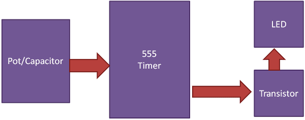
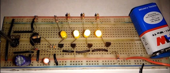
The aim of this circuit is to indicate left or right turn signal for vehicle. Two same circuits are needed, one is for left and the other is for right. Here we have made only one circuit for demonstration. In this circuit we have used astable multibirator, which is used to generate Pulse having some time period. To adjust the speed of LED blinking or indicator, we have used potentiometer. Hare we have used 4 NPN transistors for glowing indicator LEDs. Learn more about Astable Multivibrator using 555 here.
Demonstration Video for this circuit is shown below.

can i know how i can add the push button in the circuit to control the blinking of the leds.