

Audio Mixer is an essential device in Audio Electronics. The mixer mixes two or more audio signals into a one (Mono) or two output (Stereo). The audio mixer uses audio mixing process where multiple sounds are combined to form a single or multi-sound. It is a widely used process in Live concerts, televisions, films, music industries etc.
In this project, we will make Audio mixer using a single transistor which will combine two or more audio signals and produce a combined audio output. In this circuit, two audio inputs will be mixed using a single transistor to produce a mixed audio output.
Required Components
- PN2222A transistor
- 2 or more 4.7k resistor (one for each input channel)
- 2 or more .1uF ceramic disc capacitor (one for each input channel)
- 470pF ceramic disc capacitor
- .22uF ceramic disc capacitor
- 3.9k resistor
- 2.2M resistor
- 12V clean DC power supply unit. (350mA rated can be used)
- 100uF / 16V Electrolytic capacitor
- Separate Audio signals for mixing.
Here PN2222A transistor is used. Different transistor with the same ratings can also be used with this circuit like 2N3904. Below is the pin diagram of a PN2222A transistor.
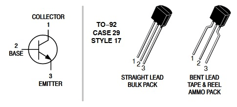
PN2222A is an NPN Silicon transistor, widely used in general purpose electronics. This transistor has 500mA of collector current and can be used for medium power amplification purposes. The case style available is TO-9.
Circuit Diagram

In this Audio Mixer circuit, transistor 2N2222A is the heart of the circuit. The emitter is connected with GND and the collector is connected with a 3.9k resistor. The output is provided across a .22uF capacitor. The other components are connected across the base of the transistor. Inputs are provided through .1uF capacitor and 4.7k resistors. We are powering the circuit using a 12V DC power supply unit.
Working of Audio Mixer Circuit
Here the transistor is amplifying three inputs which are available across the collector. The input capacitors are blocking any DC signal coming from the signal source and only allowing the AC to pass. Limiting resistors 4.7k R3, R4, and R5 are essential to mix three signals perfectly. For biasing the PN2222A transistor 2.2M resistor is used along with 470pF ceramic capacitor. Resistor R2 (3.9k) is used to provide the necessary collector current required for amplification purpose, and the output ceramic capacitor of .22uF is used to block the DC and only allowing amplified AC signal. 100uF, 16V Electrolytic capacitor is added for smooth DC supply and decoupling.
We can listen mixed audio signal directly if we connect low power headphone across the .22uF capacitor. For additional amplification, other external amplifiers can be connected across the circuit. Check here various Audio Amplifier Circuits.
Testing the Audio Mixer Circuit
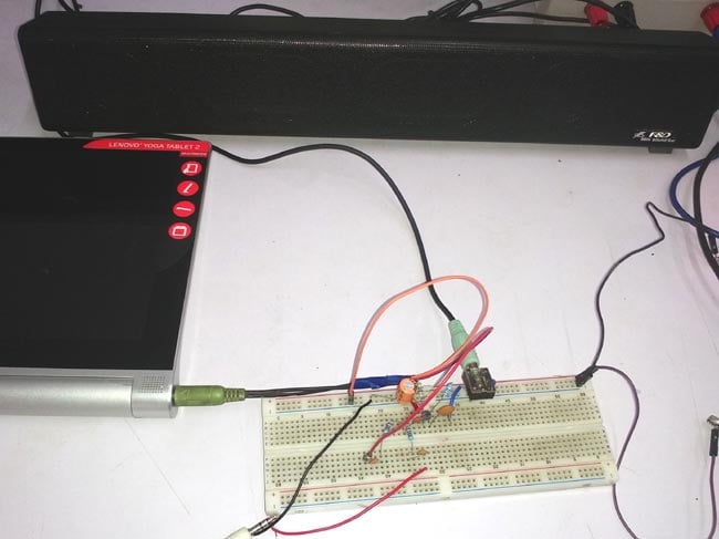
To test the circuit we used an Audio amplifier and connected it across the output. Although the circuit has option for three input channels, but here only two individual signals are provided. We gathered every component and made it on the breadboard like in the image shown below. We provided two input signals, one from the laptop and another one from the Android tablet. Then the two signals are mixed by the circuit and amplified at the output.
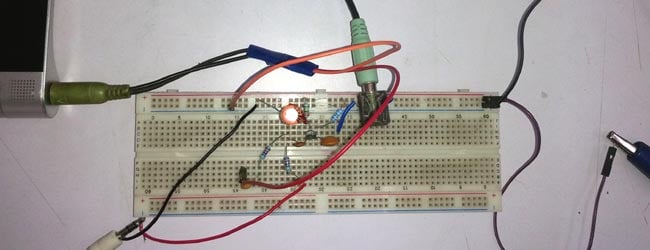
In the below images, we can see that the two inputs are connected using a 3.5mm audio jack and mixed together. We added a 3.5mm socket on the breadboard to connect an Audio Amplifier sound Bar. Whole circuit is powered by the Bench power supply with 12V.
All the connections can be seen in the below images-
You can check the working of Audio Mixer Circuit in the Video given below. The circuit is working really well and there is no audible noise. We can also add multiple outputs to the circuit.
Further Modifications
The circuit can be further modified and improved by following below points –
- Circuit can be made on PCB or on small Vero-board to minimize the noise.
- Additional buffers and filters can be added in both the input channels as well as in the output.
- If we connect individual potentiometer in each channel we can control the volume of each audio signal.
This is how two or more sounds can be mixed easily with a very simple circuit. To learn more about Audio related circuit, just follow the link.
Comments
Dear Sourav, thanks ! Awesome project. It's my first electronic audio project ever and I'm amazed it's working well!
I have four short questions to improve the project as well as my understanding of the project :
1/ is there a way to reduce the high frequency noise that comes out from the mix? Or is it maybe the consequence of some connecting I may have performed wrong ?
2/ is there a way to amplify further the output signal with some additional transistor in the circuit or would that work only with an additional amplification module ? (in that case which one would you advise ?). Indeed, by connecting passive headphones to the output, the signal intensity is unfortunately really low.
3/ what is the rational in choosing the values of the resistance and the condensators? Could you explain ?
4/ I did not manage to find 0,1 microF ceramic condensator at the input level. I used instead 2,2 microF electrolyte condensators. It works well but I'm wondering what would be the effect if I used the same condensators as yours. Could this difference explain the high frequencies noise I get in my circuit ?
once again thanks a lot for this great circuit !
all best
kororiev

i'd like to ask about how could i remove noise produced when i connect sim800L to amplifier since it happen when i connect amplifier input to SPKP with common ground for both circuit and arduino ..i get a lot of noise , but when connect my headphone to SPKP&SPKN i get pure sound with no noise ... i tried to use passive low pass filter to prevent any noise due to GSM freq (850 MHz, 1900 MHz)and allow Audio voice frequency.... so any suggestion pleas ?
----------------------------Notice --------------------- i can't connect SPKP to input of amplifier and connect SPKN to amplifier ground since it produce GSM error so i have to connect only SPKP to input of amplifier