

Every single circuit designer uses different techniques to remove noises from their circuit design. Noise is one of the main issues while building any circuit specially related to Audio or Power Electronics, but today, we will make a circuit which will produce noises. A special type of noise denoted as White noise.
What is white noise?
The term White came from the White Light. A white light is a mixture of all lights in equal density. So like white light is the mixture of all lights, White noise is a random signal which has an equal density of different frequencies. But there is a difference between White Light and White noise. The light which is white by appearance does not have flat power spectral density, whereas White noise has a constant power spectral density.
A simple example of white noise is when the Radio does not capture any radio station, we can hear the white noise. In this project, we will build a Simple White Noise Generator Circuit using a single transistor, two resistors, and one Zener diode and Electrolytic Capacitor.
Use of White Noise Generator
White noise has a wide range of usage.
- It is widely used in Music Production.
- White noise is useful to obtain the impulse response of an electrical circuit. It is a part of Electronics engineering.
- White noise has random frequency thus we can generate random numbers from white noise.
- It has medical implementation too. White noise is used in Tinnitus Treatment.
- Sound and Acoustic engineers use white noise to balance sound equalization in a concert or other performance venue.
Required Components
To make this White noise generator we need the following items-
- BC108 transistor.
- 10V Zener diode (1N4740A)
- 68k resistor
- 6.8k resistor
- 4.7uF 35V Electrolytic Aluminium Capacitor
- Three Single berg male header
- Small copper clad board or veroboard
- Soldering iron
- Soldering wire
- Any power supply with an output voltage between 26V to 30.
Transistor BC108
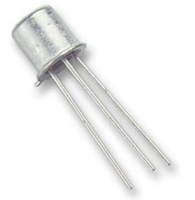
Here is the main transistor. We have selected BC108 for this purpose, another preferable choice is 2N3643. Although any equivalent transistor with the same rating will work fine as expected.
Transistor with TO-18 Metal Can package is very common in electronics compared to typical plastic body found in BC547 or similar. BC108 is an NPN Silicon Planar Epitaxial Transistor with 25v Collector-Emitter Voltage, 30V Collector-Base Voltage and 5V Emitter-Base voltage with 200mA continuous Collector Current.
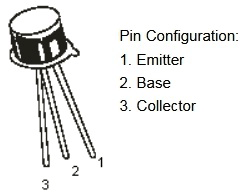
The pinout diagram is given in the below image-
Zener Diode
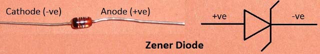
Another important component is the Zener diode, which is an essential part of the noise generator circuit. We need to check about the polarity of the diode, otherwise, the circuit will not work.
Simple White Noise Generator Schematic

The circuit is simple. There are one output pin for noise output and two pins for power supply, Vin and GND.
Working of the White Noise Generator Circuit
Transistor BC108 is getting the bias current through the 10V Zener diode which is placed in reverse bias with the transistor base. The 10V Zener diode is acting as a Noise source. Other two resistors are connected for current control. The 4.7uf Capacitor is working as a filter capacitor. The circuit needs fairly high voltage to provide noise at the output. We provided 26V as the input voltage of the circuit.
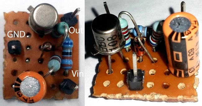
We made the circuit in a small veroboard.
Testing the circuit
We connected an Oscilloscope at the output of the circuit to see the noise output level.
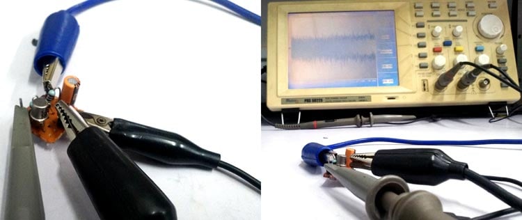
We can also see the noise output level of the circuit in the video given at the end. In the video, we can see that the wave is providing high-frequency noises.
We also captured the signals at random time.

In the above images, we captured the noise signal at four random times. We can see that in those four signals there are different frequency waves available. We set the Oscilloscope capture timing to 100uS and set the division to 500mV. We also set the cursor at 1V pk to pk and we can see the voltage magnitude is quite stable.
Important Notes
- Make the Circuit on PCB board.
- Make sure the length of the traces is short.
- Use a clean power supply. The noisy power supply could affect the output.
- Be careful about the Zener diode orientation.
- Add an Amplifier to make the noise audible.
