

The flight controller is the brain of a drone as it monitors and controls everything the drone does. KK2.1.5 and CC3D are widely used flight controllers in drones. In our previous tutorial, we have used KK2.1.5 Flight Controller to fly a drone. You don’t require any PC to set up the KK2.1.5 flight controller as it comes with an inbuilt screen and we can set up this flight controller using buttons. But many users prefer CC3D because of its "tight" or "responsive" control and another fact is that it's open-source in terms of programming and board design. So, in this project, we are going to use a CC3D flight controller with the same drone. The CC3D is slightly more advanced, with more options and a steady supply of community support, but it demands a better understanding of what you're doing in terms of copters and controls. So, let’s get started and see how the CC3D flight controller performs. Explore beginner to advanced drone projects with step-by-step guides and schematics.
Introduction to CC3D Flight Controller
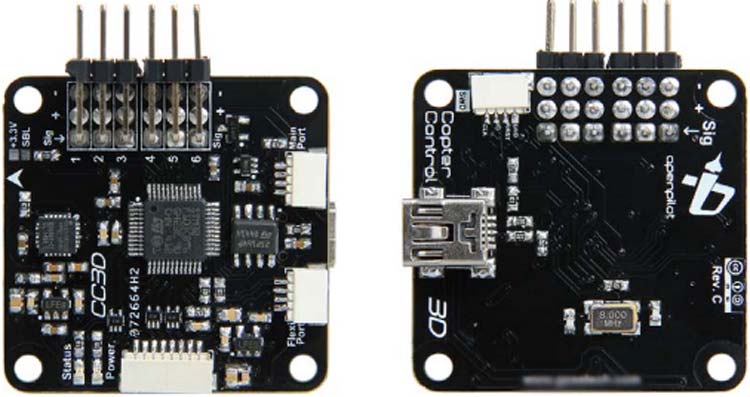
CC3D flight controller was developed by OpenPilot. The first version board, the Copter Control, was discontinued in 2012 due to a shortage of gyro sensors required for stabilization. After then, the board was redesigned and launched with a better gyro sensor that is less impacted by temperature variations. This new version board is known as the CC3D, and it is identical to the original Copter Control for the gyro sensor update.
This OpenPilot CC3D EVO Flight Controller Side Pin card has a smooth feature that allows it to work with satellite receivers directly without the use of any additional cables. It also works with S BUS but in this project, we are going to use PWM. The CC3D flight controller is powered by a 32-bit STM32 processor with 128kb Flash and 20kb RAM. Both the gyro and accelerometer use 3-axis MEMs technology. The card can be programmed in Windows, Mac OS X, or Linux using USB and OpenPilot software and no drivers are required. OpenPilot is an extremely user-friendly tool that anyone, regardless of programming knowledge, may use.
Specifications
- Powerful STM32 32-bit microcontroller running at 90MIPs with 128KB Flash and 20KB RAM
- 3-axis high-performance MEMs gyros and 3-axis high-performance MEMs accelerometer and tiny 36mmx36mm 4 layer PCB for superior electrical noise reduction and flight performance.
- Software support for Windows, Mac, and Linux and direct high-speed USB support with no drivers required, a truly plug and play device.
- Spektrum satellite receiver support and Futaba S-BUS hardware support
- Innovative Flexi-port technology for superior port flexibility and 4Mbits on-board EEPROM for configuration storage
Sensors and Hardware Description
- 3-axis Gyroscope array and 3-axis Accelerometer: MPU-6000
- Supports several common RC inputs: 6 PWM channels, combined PPM, Spektrum/JR DSM2, DSMJ, DSMX satellites, and Futaba S.Bus receivers
- ReceiverPort functions (configurable): 6 PWM input channels or combined PPM stream, 4 PWM output channels
- MainPort functions (configurable): serial telemetry (default), GPS, S.Bus, Spektrum/JR satellites
- FlexiPort (configurable): serial telemetry, GPS, Spektrum/JR satellites, or I2C peripherals (under development)
- 10 PWM outputs to servos or ESC’s, or for camera stabilization
- Camera stabilization: supports up to 3-axis camera mounts with stabilization and manual control from any of configured receivers
- Onboard USB connectivity for easy configuration and USB and serial telemetry and configuration (including wireless with optional radio modules)
- Supported by powerful OpenPilot GCS and 4 Mbit onboard memory
- 3C Quaternion based complementary filter running at 500Hz
Setting up CC3D Flight Controller
We need Open Pilot Ground Control Station (Open Pilot GCS) software to configure the CC3D flight controller. OpenPilot GCS is a ground control station for the OpenPilot series of open-source flight control, telemetry modem, and autopilot boards. Firmware uploading, configuration, control, and telemetry monitoring are all possible with the help of the OpenPilot GCS Application. All OpenPilot boards are supported by this application. You can download Open Pilot GCS software for windows, Mac, and Linux.
Now, we are going to cover step by step configuration and setup of the CC3D flight controller.
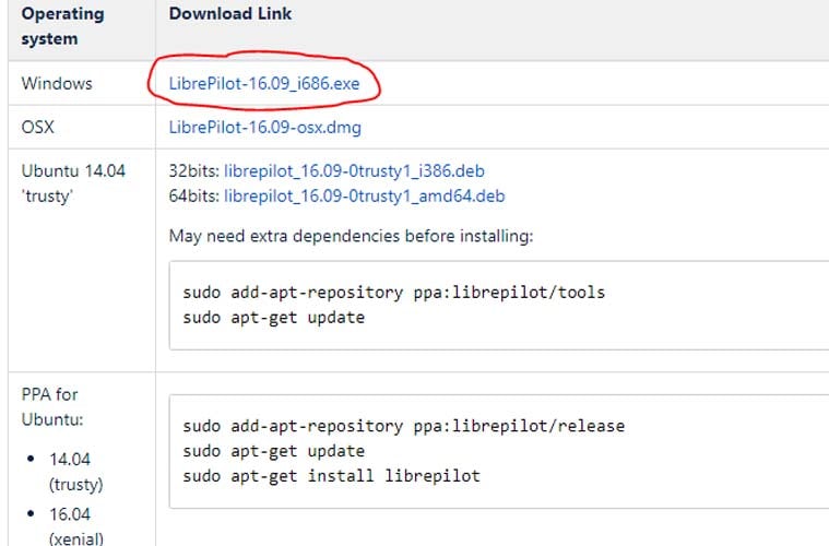
Step-1 Download the Open Pilot GCS software using this link and install the software.
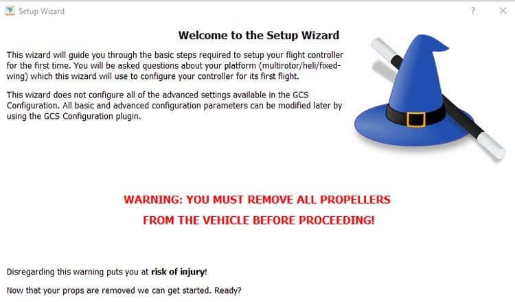
Step-2 After installation, click on Open Pilot GCS icon on your desktop and you will be greeted by the below screen. Please remove the propellers from the motors before continuing to avoid any potential harm.
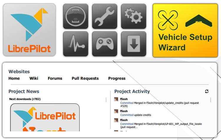
Step-3 Click on the yellow “Vehicle Setup Wizard” and the pop-up will appear, click the 'Next' button after making sure your CC3D flight controller is not linked to the PC or the batteries.
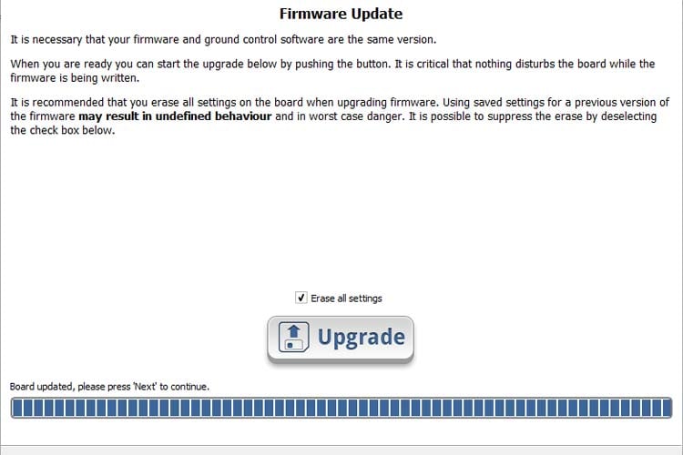
Step-4 Click the 'Upgrade' button after checking the 'Erase all settings' box. The progress bar should turn blue, and you should connect your CC3D to your PC using the USB cord as directed. Once GCS has finished updating your CC3D, click the 'Next' option.
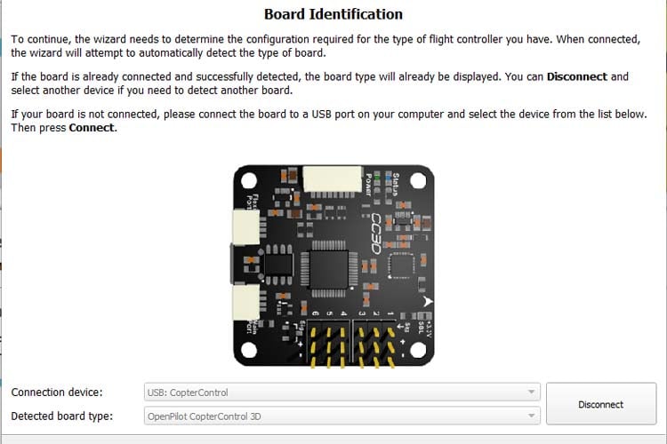
Step-5 Click next on the OpenPilot Board identification window. Your board type should be displayed here.
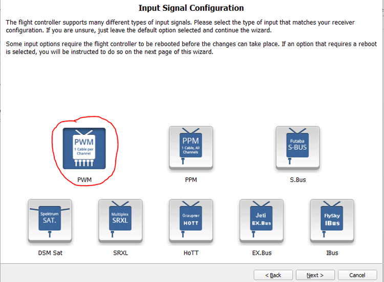
Step-6 Now, We have to choose the type of receiver input. We will choose PWM here because we are going to use FS-i6 transmitter and FS-iA6B receiver. To move on to the next screen, press 'Next.'
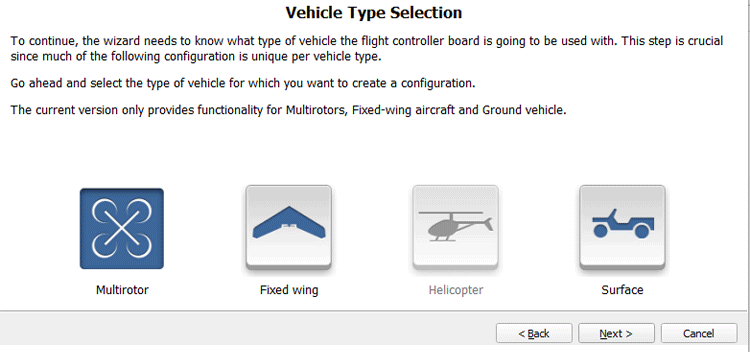
Step-7 CC3D flight controller will start booting. Now, on the Vehicle Type Selection screen, select 'Multirotor' and then hit 'Next.'
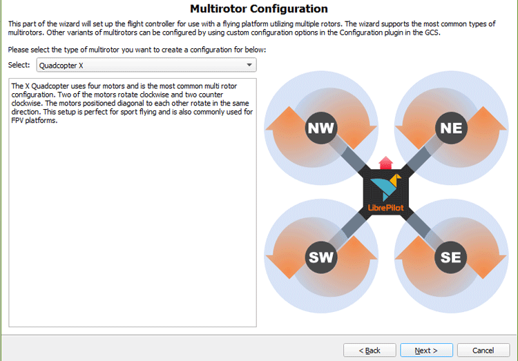
Step-8 We are going to design a quadcopter of X shape. So, we will select “Quad Copter X” on the multirotor configuration window and then click "Next".
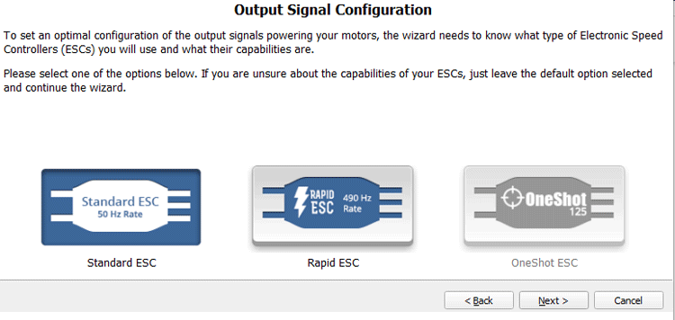
Step-9 Now, select Standard ESC 50 Hz rate because we are going to use 30A simonk ESCs.
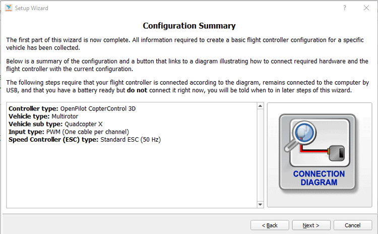
Step-10 In the Configuration Summary window, double-check that all of the settings are right. If they're wrong, go back and fix them; if not, click the 'Connection Diagram' button.
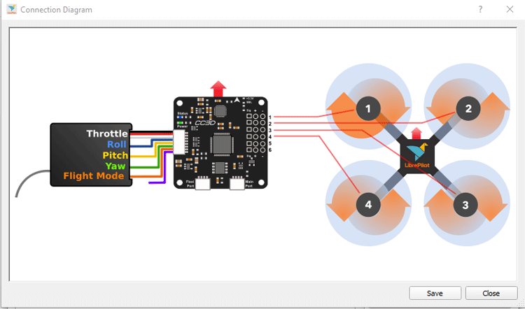
Step-11 Connect the ESC and Receiver to the CC3D as shown in the diagram, then select 'Save' to exit the diagram and move on to the next step.
Connections of CC3D Flight Controller with ESCs and FS-iA6B Receiver
Right-hand side of the CC3D board has 6 outputs out of which we will be using four only outputs to connect ESCs directly. We are going to use quadcopter so we have used only four output pins and in the below image you can see output pins are covered by red color box.
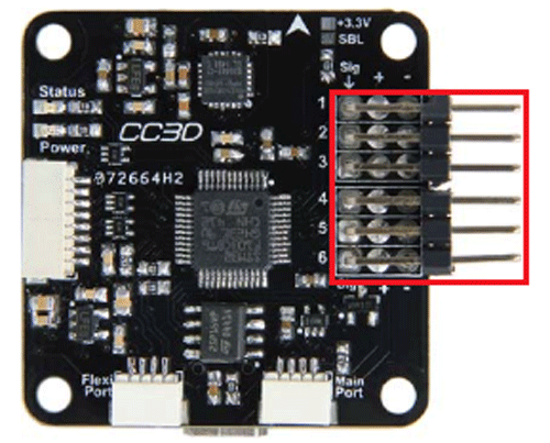
Output pins have 3 pins in each row. The rightmost pins are ground. All center pins are Vcc (5 volts). And the pins on the left are signals. Connect all the four ESCs wires to the first four output pins of the CC3D board. The connection between ESCs and CC3D board should be like the below table. The leftmost pin of the output pin is the signal pin, the middle pin is positive (Vcc) and the rightmost pin is negative (ground pin).
ESCs | CC3D Board |
Ground (Brown wire) | Ground (Rightmost pin |
Vcc (Red Wire) | Vcc (Central Pin) |
Signal (Yellow Wire) | Signal (Left pin) |
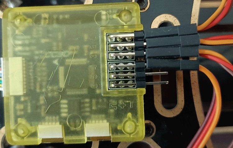
In the figure below, we can see the connection of ESCs with the CC3D flight controller. Here, we have connected only 4 ESCs because we are going to use them for the quadcopter.
In the CC3D flight controller, we have two types of input ports present on it. In the below image you can see three input ports on the CC3D board. One big port is for PWM connection and the another ports (main port and Flexi port) is for S-Bus connection.
Main Port and Flexi Port
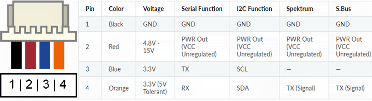
PWM Port
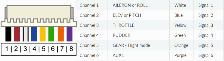
But here, we are going to use PWM so we will use a big input port only which has 8 Pins. Inputs pins are on the left side of the CC3D flight controller. There are 6 connections here, these pins will connect with the Receiver. Receiver pins and CC3D input pins should be connected as follows:
Receiver Channel | Connecting Wire Color | CC3D (Input Pins) |
Aileron (CH1) | Blue | Fourth Row |
Elevator (CH2) | Yellow | Fifth Row |
Throttle (CH3) | White (S), Red(+), Black(-) | First, Second, Third Row |
Rudder (CH4) | Green | Sixth Row |
AUX1 (CH5) | Yellow | Seventh Row |
AUX2 (CH6) | White | Eighth Row |
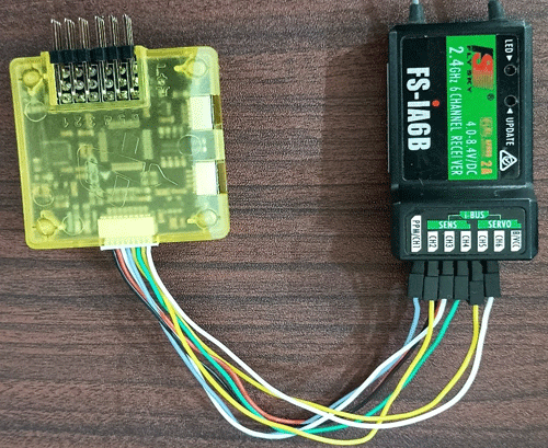
We will connect the receiver’s third channel (CH3) with three connection wires and the rest channels will be connected through a single wire only because there is no need to connect Vcc and ground for other channels. According to the above table, the receiver end connection should look like what you can see in the images below.

According to the above table, the CC3D board end connection should look like what you can see in the images below.
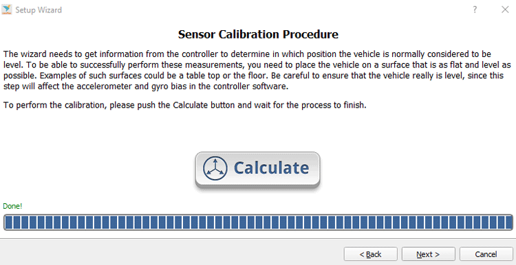
Step-12 To calibrate the flight controller, make sure your aircraft is on a level surface and press the 'Calculate' button.
Step-13 On the ESC Calibration window, read the directions very carefully and check all three boxes and then click on the start button.
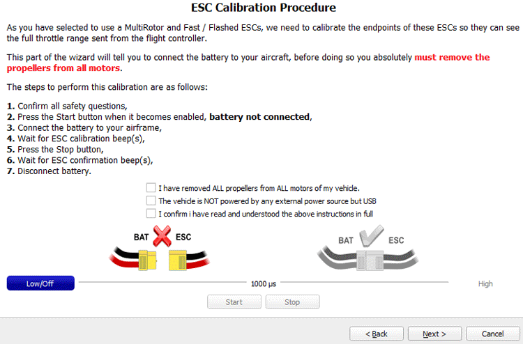
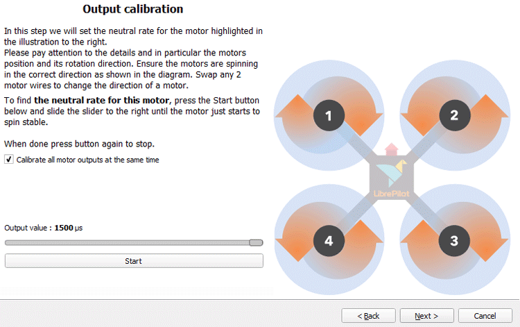
Step-14 Once you've completed the procedure and checked all three safety checkboxes, the 'Start' button will become active. Press 'Start' and follow the instructions on the screen. If you calibrated your ESC successfully, you should now see an 'Output Calibration' window. Before pressing the 'Next' button, read the instructions on the screen.
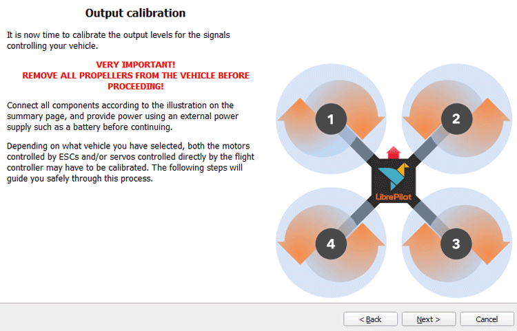
Step-15 Press and hold the 'Start' button while carefully moving the slider to the right until the motor just starts spinning. Then click on the 'Stop' button and then the 'Next' button. This procedure must be repeated for each of your motors. You should also check the direction of the rotation of the motor. All the motor’s rotation directions should be according to quadcopter X shape flight dynamics.
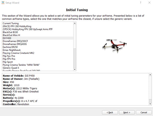
Setup-16 Select the F450 frame for the 'Initial Tuning' page because we are using the F450 frame for our quadcopter. Depending on whatever aircraft you're using, your options will vary.
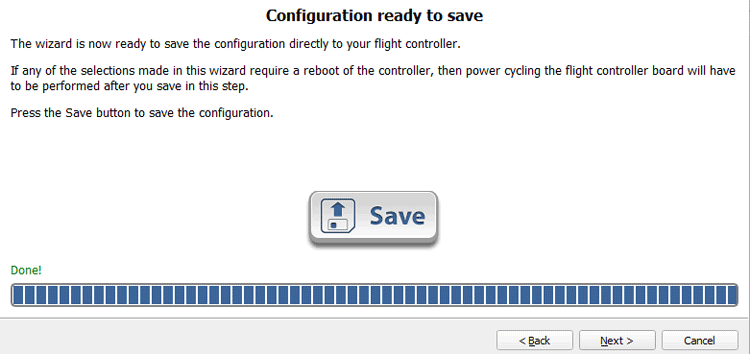
Step-17 To save all configurations and settings to CC3D, click on the "save" button.
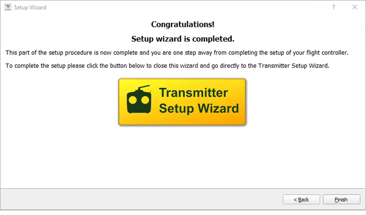
Step-18 Select the “Transmitter Wizard” Button.
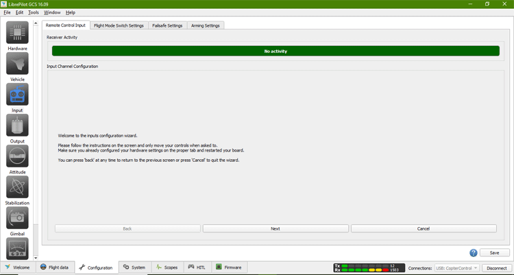
Step-19 Read all the instructions and click on the "Next" button
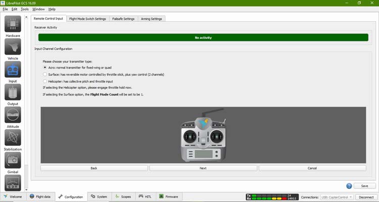
Step-20 Now select Acro normal transmitter for fixed-wing quad and select the "Next" button.
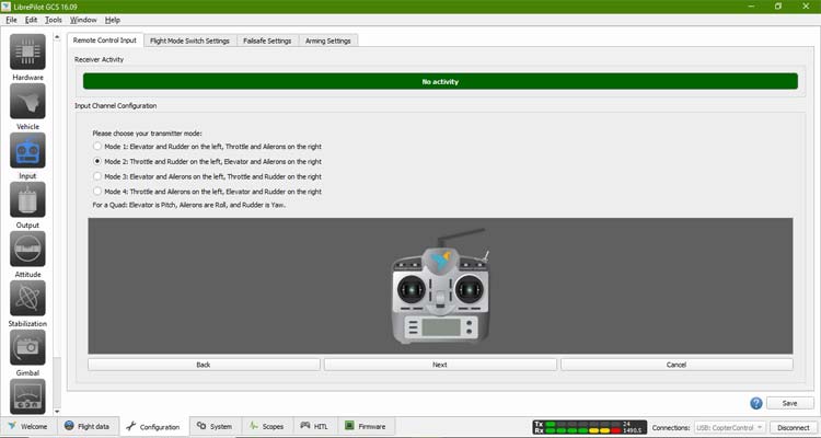
Step- 21 We have selected Mode-2 here because we feel comfortable controlling our quadcopter in mode-2, you can choose any mode as per your comfort.
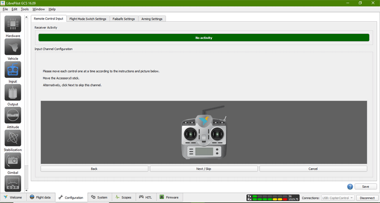
Step-22 You'll now be in the calibration window for the stick. Move the left stick up and down on the screen until the software recognizes your input. To continue, use the 'Next' button. After this, move the right stick left and right until the software recognizes it. Press the 'Next' button.
Step-23 To establish the endpoints of each input, turn both sticks in a full circle and click the flight switch back and forth.
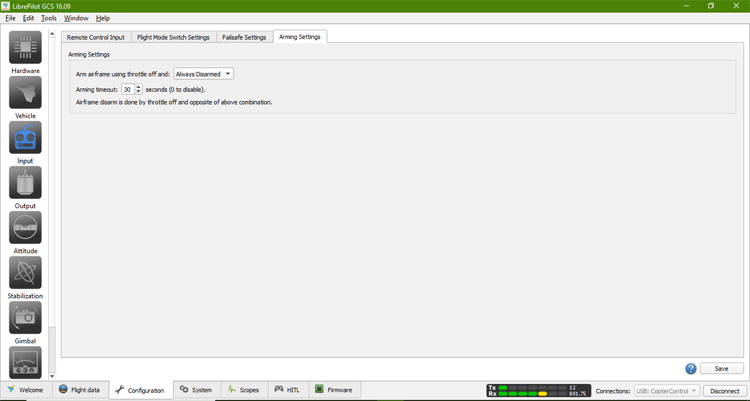
Step-24 Go to Arming Settings and make the arming and unarming changes according to you.
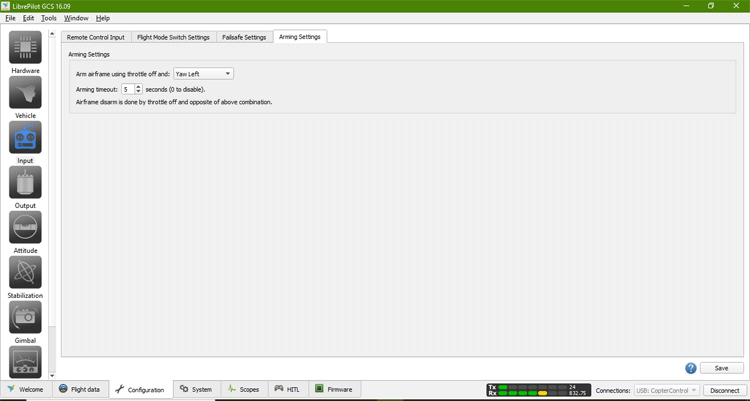
Step-25 We have selected Yaw left option, which means when we move the left stick in the left direction then only the quadcopter will be armed and it will automatically disarm after 5 seconds if we don’t apply any action on it.
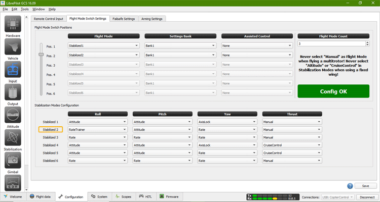
Step-26 Go to Flight mode switch settings and leave it as it is, if you want to change anything, you can change accordingly.
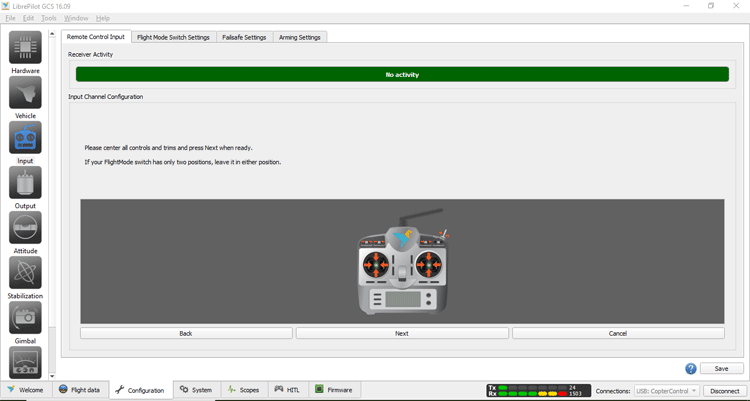
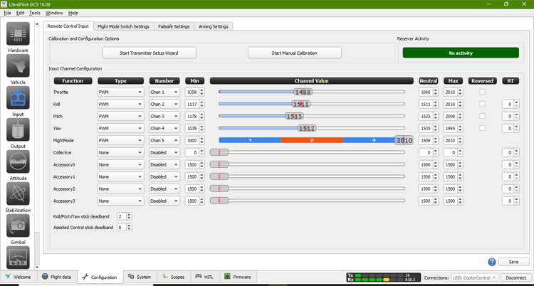
Step-27 Go to Remote control input setting and check the minimum and maximum value of throttle, roll, pitch and yaw by moving sticks of your transmitter.
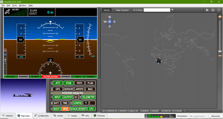
Step-28 Now, go to the flight data option and move your drone in any direction and you can see the same action on your screen, it shows how well your quadcopter is stable.
Now CC3D flight controller is fully configured and ready for flying. In this tutorial, we have designed a quadcopter with the help of an OpenPilot CC3D flight controller and have explained the configuration and setup of the CC3D flight controller for quadcopter of X shape. Hope you enjoyed the project and learned something useful. If you have any questions, please leave them in the comment section below or use our forum to start a discussion on this.
