

From the past few years the demand of low power electronic portable devices has been increased rapidly. And there are very limited options to power these small portable electronic devices like alkaline batteries or solar power etc. So here we are using a different method to generate small amount of power which uses Piezoelectric sensor. Here we will build Footstep Power Generation Circuit to generate electricity. You can learn more about Piezoelectric Effect by following this Piezoelectric Transducer Circuit.
What is Piezoelectric Effect?
Piezoelectric Effect is the ability of some piezoelectric materials (such as quartz, topaz, zinc oxide and etc.) to generate an electrical charge in feedback to the mechanical stress. ‘Piezoelectric’ word is derived from the Greek word ‘piezein’ which means to push, squeeze and press.
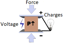
Also, the piezoelectric effect is reversible, which means when we apply mechanical stress to the piezoelectric material we receive some electrical charge on output. And, when we apply electricity to the piezoelectric material, then it compresses or stretch the piezoelectric material.
Piezoelectric effect is used in various application that involves
- Production and detection of sound
- Generation of high voltage
- Electronic Frequency generation
- Microbalances
- Ultra-fine focusing of optical assemblies
- Everyday applications like cigarette lighters
Resonator also use Piezoelectric effect.
Piezoelectric Materials
Number of piezoelectric materials are available now, even natural and man-made. Natural piezoelectric materials include quartz, cane sugar, Rochelle salt, topaz tourmaline and etc. Man-made piezoelectric material includes barium titanate and zirconate titanate. There are some material given in the below table in the category of natural and synthetic:
|
Natural Piezoelectric Material |
Synthetic Piezoelectric Material |
|
Quartz (most used) |
Lead zirconate titanate (PZT) |
|
Rochelle Salt |
Zinc Oxide (ZnO) |
|
Topaz |
Barium Titanate (BaTiO3) |
|
TB-1 |
Piezoelectric ceramics Barium titanate |
|
TBK-3 |
Calcium barium titanate |
|
Sucrose |
Gallium orthophosohate (GaPO4) |
|
Tendon |
Potassium niobate (KNbO3) |
|
Silk |
Lead titanate (PbTiO3) |
|
Enamel |
Lithium tantalite (LiTaO3) |
|
Dentin |
Langasite (La3Ga5SiO14) |
|
DNA |
Sodium tungstate (Na2WO3) |
Components Required
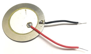
- Piezoelectric Sensor
- LED (Blue)
- Diode (1N4007)
- Capacitor (47uF)
- Resistor (1k)
- Push-button
- Connecting Wires
- Breadboard
Footstep Power Generation Circuit Diagram

A piezoelectric sensor is made up of piezoelectric material (quartz-most used). It used to convert the mechanical stress into electrical charge. The output of the Piezoelectric Sensor is AC. We need a full bridge rectifier to convert it into DC. The output voltage of the sensor is less than 30Vp-p, you can feed the output of piezoelectric sensor or can store it into battery or other storage devices. The impedance of the piezoelectric sensor is less than 500 ohm. The operating and storage temperature range is -20°C~+60°C and -30°C~+70°C respectively.
After making connections as per the Piezoelectric Sensor circuit diagram, when we provide mechanical stress to the piezoelectric sensor it generates voltage. The output of the piezoelectric sensor is in AC form. For converting it from AC to DC we are using a full bridge rectifier. The output of the rectifier is connected across a 47uF capacitor. The voltage generated by the piezoelectric sensor get stored in the capacitor. And, when the push-button is pressed all the stored energy is transferred to the LED and LED turns ON till the capacitor get discharged.
In this circuit, the LED is glowing for a fraction of seconds. To increase the ON time of LED you can increase the capacitor rating, but it will take more time to charge. Even, you can connect more piezoelectric sensor in series to generate more electrical energy. Also, the diode is used for blocking the current to flow from capacitor to piezoelectric sensor and the resistor is a current limiting resistor. The LED can also be directly connected to the Piezoelectric sensor but it will turn off in a moment as there will be no capacitor to hold the current.
Demonstration video for this Foot Step Power Generation System is given below.
Comments
The D1 is mandatory to prevent the capacitor form discharging back into the rectifier bridge
C1 cannot discharge into the diode bridge because all the diodes in the bridge are reverse-biased when viewed from C1. They are only forward-biased (in pairs) when viewd from the piezoelectric sensor. Max is right.
Can you put another video with full connecting process
where to connect the led and resistor
What is the value of the full wave bridge rectifier??
Hi there,
I found your tutorial about the Footstep Power Generation Circuit using a piezoelectric sensor and I’m trying to replicate it. It’s a great project, thank you for sharing it!
I have a couple of questions about the actual breadboard setup in your photo:
-
Diode bridge: In your circuit description you mention using a full bridge rectifier to convert AC to DC, but in the photo I only see a single 1N4007 diode. Did you use just one diode for half-wave rectification in the final build? If so, would you recommend using a proper 4-diode bridge rectifier instead? Could you kindly share a schematic of the version with the full bridge, or explain how to connect it?
-
Components identification: There is a blue cylindrical component next to the 47uF black capacitor. Is that another capacitor? It’s sometimes mistaken for a buzzer, but I assume it’s for smoothing the output. Could you confirm its value and purpose?
-
Performance: With the setup shown in the picture, how long does the LED typically stay on after one press on the piezo? Would adding a bridge rectifier + bigger capacitor make a noticeable difference?
I’d really appreciate any clarification or tips you can share. If you have an updated version with the bridge rectifier I’d love to build that one to be sure I’m doing it right.
Thanks so much for your time and for the awesome project!

I like this little circuit, however, I do not see the need for diode D1. Is the idea to use a lower leakage diode for D1 compared to the diodes of the rectifier bridge?