

Certain crystals like Barium titanate, Quartz, Lithium tantalite, etc. have the property of producing electricity on applying a force or pressure over them under specific arrangement. Also, they can work in inverse by transforming the electrical signal applied across them into vibrations. Hence, they are used as transducers in many applications. They are called as piezoelectric materials. Hence, a Piezoelectric Transducer produces voltage when applying a force over them and vice versa. First, let us look at some of the applications of Piezoelectric Transducer followed by the definition.
Piezoelectric Effect:
1. Mechanical stress analyzer:
The major application is stress analyzer for columns in building where the proportional voltage produced upon stress over crystal is measured and the corresponding stress can be calculated.
2. Lighters:
Gas burner lighter and cigarette lighter also abide the same rule of piezoelectric effect which produces electric pulse upon the force produced by sudden impact of trigger over the material inside them.
Piezo electric effect is defined as the change in electric polarization that is produced in certain materials when subjected to mechanical stresses.
Inverse Piezoelectric effect:
1. Quartz Watch:
Inside our watch, there is quartz resonator which works as oscillator. The element is silicon dioxide. The electric signal applied across the crystal makes it to vibrate periodically which in turn regulates the gears inside our watch.
2. Piezo Buzzers:
Buzzers are widely used in many applications like car reverse indicator, Computers and etc. In this case, on applying of voltage at certain magnitude and frequency across the above mentioned crystal they tend to vibrate. The vibration can be diverted into a housed space with small opening making it into audible sound.
Inverse Piezo electric effect is defined as the strain or deformation produced in certain materials when subjected to electric field.
Piezoelectric Transducer:

Above is a cheap three terminal piezoelectric transducer used in 12V Piezo Buzzer that produces sound with the below circuit arrangement. Where the black housing becomes the structure to create audible sound.


Converting Force into Electricity Using Piezoelectric Transducer:
Let us try to experiment the piezoelectric effect by converting a force into small voltage signal using the piezoelectric transducer disc. Then let us try to store the energy produced through the force or pressure.
Soldering the terminals:
Soldering the wire to the piezoelectric transducer is the main part of using them. Be careful not to overheat the surface since it melts off even at low temperature for a few seconds. Hence try to melt the lead in soldering iron and drop the molten solder over the surface. For this operation, terminals positive and negative will be enough and can be seen in the picture above.
Operation:
The Piezoelectric Transducer produces a discontinuous or alternating output on applying repeated tapping force over it. Hence it has to be rectified to make it storable or usable DC. Hence for a higher rectifying efficiency of 80% or above, we are going to use full wave rectifier. Either we can use a combination of four diodes in bridge configuration or a package with inbuilt bridge diode like RB156. Here is the reference to build Full Wave Rectifier with Filter.
Hence the same concept is applied here where the alternating output from the piezoelectric transducer is converted into DC and stored inside the output capacitor. The stored energy is then dissipated through an LED with controlled output. Hence, the dissipation of stored energy will be visible.
Piezoelectric Transducer Circuit Diagram:
The below is the schematic diagram of the Piezoelectric Transducer Circuit where the energy stored in capacitor will be dissipated only when the tactile switch is closed.

The capacitor used in the output can be increased further to increase the storage capacity but however the number of piezoelectric transducers also has to be increased. Hence, here it is 47uF.
Working:
As explained in the simulation above the connections are made in the Breadboard. But, the reason for using two piezoelectric transducers is to increase the amount of energy produced in a short time interval. Initially, we give continuous tapping over the transducers.
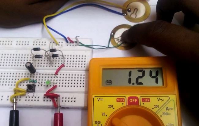
Once the required voltage level is reached, we press the tactile switch and the LED glows for a moment.
The reason for the LED blink as below is that the 47uF capacitor used can store only that much energy to blink the LED for a few seconds. The amount of energy produced and stored can be increased by increasing the number of transducers and the capacitor value. The video below demonstrates the above done process in steps.

Is there any way to produce or increase its current?