
A mixer is a special type of electronic circuit that combines two signals (periodically repeating waveforms). Mixers find a lot of use in audio and RF systems and rarely used as simple analog ‘computers’. There are two types of Analog Audio Mixers - Additive Mixers and Multiplicative Mixers.
1. Additive Mixers
Like their name suggests, additive mixers simply add together the values of two signals at any instant, which results in a continuous waveform at the output that is the sum of the values of the individual waveforms.
The simplest additive mixer is simply two signal sources connected to two resistors in the following fashion:

The resistors prevent the signal sources from interfering with each other, the addition happens at the common node, not at the signal sources themselves. The beauty of this method is that a weighted sum is possible, depending on the individual resistor values.
Mathematically speaking,
z = Ax + By
Where ‘z’ is the output signal, ‘x’ and ‘y’ are the input signal and ‘A’ and ‘B’ are the ratiometric scaling factors i.e. the resistor values relative to each other.
For example if one of the resistor values is 10K and the other is 5K, A and B become 2 and 1 respectively, since 10K is twice 5K.
Of course, more than two signals can be combined together using this audio mixer.
Constructing a Simple Additive Mixer
Parts required:
1. 2x 10K resistors
2. 1x 3.3K resistor
3. A two channel signals source
Circuit Diagram:

With the two 10K resistors, the output is simply the sum of the input signals. A and B are both unity, since the two scaling resistors are the same.

The yellow and blue waveforms are the inputs, and the pink waveform is the output.
When we replace one of the 10K resistors with a 3.3K resistor, the scaling factors become 3 and 1 and one third of one signal gets added to the second.
The mathematical equation is:
z = x + 3y
Below figure shows the resulting output waveform in pink, and the inputs in yellow and blue.

Application of Additive Mixers
The most striking hobbyist use of simple mixers like this comes in the form of a headphone equalizer or a ‘mono to stereo’ converter, which converts the left and right channels from a 3.5mm stereo jack to a single channel using two (usually) 10K resistors.
2. Multiplicative Mixers
Multiplicative mixers are a little more interesting – they multiply two (or perhaps more, but that’s difficult) input signals and the product is the output signal.
Addition is simple, but how do we electronically multiply?
There’s another little mathematical trick that we can apply here, called a logarithm.
A logarithm is basically asking the question – to what power must a given base be raised to give the result?
In other words,
2x = 8, x = ?
In terms of logarithms, this can be written as:
log2x = 8
Writing numbers in terms of an exponent of a common base enables us to use another basic mathematical property:
ax x ay = ax+y
Multiplying two exponents with a common base is equivalent to adding the exponents and then raising the base to that power.
This has the implication that, if we apply a logarithm to two signals, adding them together and then ‘taking’ an antilog is equivalent to multiplying them!
The circuit implementation can get a little complicated.
Here, we shall discuss a rather simple circuit called a Gilbert cell mixer.
Gilbert cell mixer
Below figure shows the Gilbert cell mixer circuit.

The circuit may look very intimidating at first, but like all complicated circuits this one can be broken down into simpler functional blocks.
Transistor pairs Q8/Q10, Q11/Q9 and Q12/Q13 form individual differential amplifiers.
Differential amplifiers simply amplify the differential input voltages to the two transistors. Consider the simple circuit shown in below figure.

The input is in differential form, between the bases of transistors Q14 and Q15. The base voltages are the same, so are the collector currents and the voltage across R23 and R24 are the same, so the output differential voltage is zero. If there is a difference in base voltages, the collector currents differ, setting up different voltages across the two resistors. The output swing is larger than the input swing, thanks to transistor action.
The takeaway from this is that the gain of the amplifier depends on the tail current, which is the sum of the two collector currents. The greater the tail current, the greater the gain.
In the Gilbert cell mixer circuit shown above, the top two diff amps (formed by Q8/Q10 and Q11/Q9) have cross connected outputs and a common set of loads.
When the tail currents of the two amplifiers is the same and the differential input A is 0, the voltages across the resistors is the same and there is no output. This is also the case when the input A has a small differential voltage, since the tail currents are the same, the cross-connection cancels out the overall output.
Only when the two tail currents are different, the output voltage is a function of the difference of the tail currents.
Depending on which tail current is larger or smaller, the gain can be positive or negative (relative to the input signal), i.e. inverting or non-inverting.
The difference in tail currents is brought about using another differential amplifier formed by transistors Q12/Q13.
The overall result is that the output differential swing is proportional to the product of the differential swings of inputs A and B.
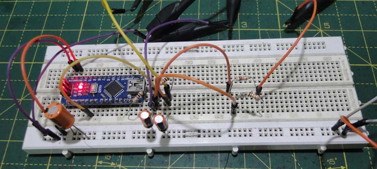
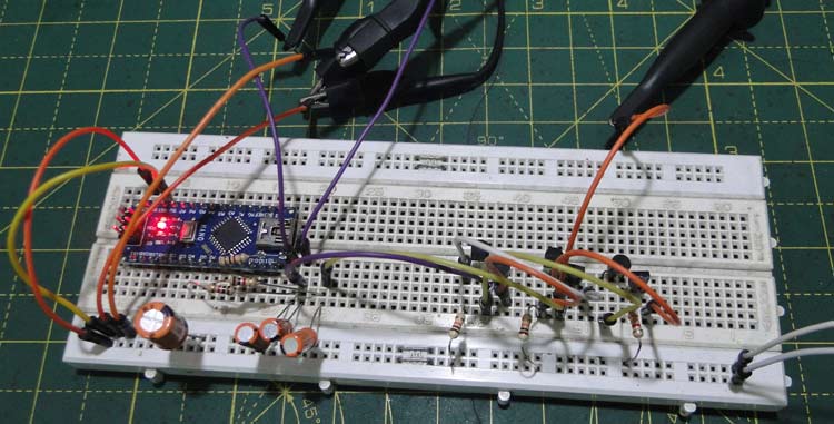
Constructing a Gilbert Cell Mixer
Parts Required:
1. 3x 3.3K resistors
2. 6x NPN transistors (2N2222, BC547, etc.)
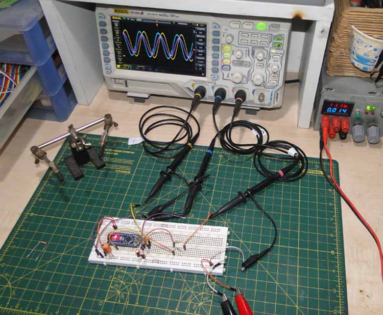
Two phase shifted sine waves are fed into the inputs (shown by the yellow and blue traces), and the output is shown in pink in below image, compared to the scope’s math multiply function, whose output is the purple trace.

Since the oscilloscope does ‘real time’ multiplication, the inputs had to be AC coupled so that it calculated the negative peak too, since the inputs to the actual mixer were DC coupled and it could handle multiplication of both polarities.
There is also a slight phase difference between the mixer output and the scope trace, since things like propagation delays have to be considered in real life.
Applications of Multiplicative Mixers
The biggest use for multiplicative mixers is in RF circuits, to demodulate high frequency waveforms by mixing it with an intermediate frequency waveform.
A Gilbert cell like this one is a four quadrant multiplier, meaning that multiplication in both polarities is possible, following the simple rules:
A x B = AB
-A x B = -AB
A x -B = -AB
-A x -B = AB
Arduino Sine Wave Generator
All the waveforms used for this project were generated using an Arduino. We have previously explained the Arduino function generator circuit in detail.
Circuit Diagram:

Code explanation:
The setup section creates two lookup tables with the values of the sine function, scaled to an integer from 0 to 255 and one phase shifted by 90 degrees.
The loop section simply writes the values stored in the lookup table to the PWM timer. The output of the PWM pins 11 and 3 can be low pass filtered to get a nearly perfect sine wave. This is a good example of DDS, or direct digital synthesis.
The resulting sine wave has a very low frequency, limited by the PWM frequency. This can be fixed with some low level register magic. Complete Arduino code for sine wave generator is given below:
Arduino code:
#define pinOne 11
#define pinTwo 3
#define pi 3.14
float phase = 0;
int result, resultTwo, sineValuesOne[100], sineValuesTwo[100], i, n;
void setup()
{
  pinMode(pinOne, OUTPUT);
  pinMode(pinTwo, INPUT);
  Serial.begin(115200);
  for(phase = 0, i = 0; phase <= (2*pi); phase = phase + 0.1, i++)
  {
    result = (50 * (2.5 + (2.5 * sin(phase))));
    sineValuesOne[i] = result;
    resultTwo = (50 * (2.5 + (2.5 * sin(phase - (pi*0.5)))));
    sineValuesTwo[i] = resultTwo;
  }
  n = i;
}
void loop()
{
  for(i = 0; i <= n; i++)
  {
    analogWrite(pinOne, sineValuesOne[i]);
    analogWrite(pinTwo, sineValuesTwo[i]);
    delay(5);
  }
}
Conclusion
Mixers are electronic circuits that add or multiply two inputs. They find extensive use in audio, RF and occasionally as elements of an analog computer.
Comments
It was missing DC operation point resistors.
New simulation:


Hi,
Here is LT Spice simulation made following instructions
However, output is pretty much straight zero.
Why?
Best regards
Dragan Stanic