
Previously we have covered many types of Home automations using different technologies like DTMF Based Home Automation, PC Controlled Home Automation using Arduino, Bluetooth Controlled Home Automation. In this project, we are using IR based wireless communication for controlling home appliances. In this project, Arduino is used for controlling whole the process. We send some commands to the controlling system by using IR TV/DVD/MP3 remote for controlling AC home appliances. After receiving signal from IR remote, Arduino sends related signal to relays which are responsible for switching ON or OFF of the home appliances through a relay driver.
Working Explanation:
Working of this project is easily understandable. When we press any button of IR Remote then remote sends a code in form of train of encoded pulses using 38Khz modulating frequency. These pulses are received by TSOP1738 sensor and read by Arduino and then Arduino decodes received train of pulse into a hex value and compares that decoded value with the predefined hex value of the pressed button. If any match occurs then Arduino perform relative operation and the corresponding result is also displayed on 16x2 LCD by using appropriate commands. Here in this project we have used 3 bulbs of different colors, for demonstration which indicates Fan, Light and TV.
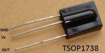
There are many types of IR Remote are available for different device but most of them are worked on around 38KHz Frequency signal. Here in this project we control home appliances using IR TV remote. For detecting IR remote signal, we use TSOP1738 IR Receiver. This TSOP1738 sensor can sense 38Khz Frequency signal. The working of IR remote and the TSOP1738 can be covered in detail in this article: IR Transmitter and Receiver
Components:
- Arduino UNO
- TSOP1738
- IR TV/DVD Remote
- ULN2003
- Relays 5 volt
- Bulb with holder
- Connecting wires
- Bread board
- 16x2 LCD
- Power supply
- PVT
- IC 7805
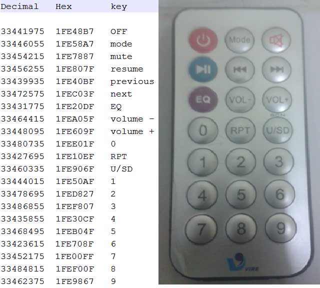
Here in this project we have used 7, 8 and 9 number button of IR remote, for controlling Fan, Light and TV respectively and ON/OFF button (Power button) is used for turning ON and OFF all the appliances simultaneously.
Here we have used toggle [EVEN ODD] method for ON and OFF the single home appliance. Toggle method is nothing but to get that whether the button is pressed even no of times or the odd no of times. This is found by getting the reminder after dividing it by 2 (i%2), if there is some reminder then device will be turned ON and if reminder is 0 then it will be turned OFF. Suppose Key 7 is pressed on the remote then remote sends a signal to Arduino through TSOP IR Receiver. Then Arduino decode it and store the decoded value into the results variable. Now results variable has a hex value 0x1FE00FF, after matching it with the predefined hex value of key 7 (see above image), Arduino turns ON the Fan. Now when we press the same key (key 7) again then IR sends the same code. Arduino gets same code and matched with same code like before but this time Fan turned OFF because of toggling the bit [EVEN ODD] (i%2).
Decoding IR Remote Control Signals using Arduino:
Here is a list of a DVD NEC type Remote decoded output codes:
If you don’t know the Decoded output for your IR remote, it can be easily found, just follow these steps:
- Download the IR remote library from here https://github.com/z3t0/Arduino-IRremote.
- Unzip it, and place it in your Arduino ‘Libraries’ folder. Then rename the extracted folder to IRremote.
- Run the below program from your Arduino and open the Serial Monitor window in Arduino IDE. Now press any IR Remote button and see the corresponding decoded hex output in Serial Monitor window.
 * IRremote: IRrecvDemo - demonstrates receiving IR codes with IRrecv
 * An IR detector/demodulator must be connected to the input RECV_PIN.
 * Version 0.1 July, 2009
 * Copyright 2009 Ken Shirriff
 * https://arcfn.com
 */
#include <IRremote.h>
int RECV_PIN = 11;
IRrecv irrecv(RECV_PIN);
decode_results results;
void setup()
{
  Serial.begin(9600);
  irrecv.enableIRIn(); // Start the receiver
}
void loop() {
  if (irrecv.decode(&results)) {
    Serial.println(results.value, HEX);
    irrecv.resume(); // Receive the next value
  }
  delay(100);
}
The above program is taken from IRremote library’s ‘examples’ folder, you can check out more examples to learn more about using the IR remote. So that’s how we decoded the IR remote output.
Circuit Description:
Connections of this circuit is very simple here a liquid crystal display is used for displaying status of home appliances which is directly connected to arduino in 4-bit mode. Data pins of LCD namely RS, EN, D4, D5, D6, D7 are connected to arduino digital pin number 6, 7, 8, 9, 10, 11. And output pin of TSOP1738 is directly connected at digital pin number 14 (A) of Arduino. And Vcc pin is connected a +5 volt and GND pin connected at Ground terminal of circuit. A relay driver namely ULN2003 is also used for driving relays. 5 volt SPDT 3 relays are used for controlling LIGHT, FAN and TV. And relays are connected to arduino pin number 3, 4 and 5 through relay driver ULN2003 for controlling LIGHT, FAN and TV respectively.

Code Description:
In programming part of this project First of all in programming we includes library for IR remote which is easily available at Google. And define pin and declare variables.
#include <IRremote.h>
const int RECV_PIN=14;
IRrecv irrecv(RECV_PIN);
decode_results results;
And then include a header for liquid crystal display and then we defines data and control pins for LCD and home appliances.
#include<LiquidCrystal.h>
LiquidCrystal lcd(6,7,8,9,10,11);
#define Fan 3
#define Light 4
#define TV 5
After it we need to initialize the LCD and give direction of pin that are used for fan , light and TV.
void setup()
{
  Serial.begin(9600);
  lcd.begin(16,2);
  pinMode(Fan, OUTPUT);
  pinMode(Light, OUTPUT);
  pinMode(TV, OUTPUT);
As already explained, below part of the code is used to compare the received hex value to already defined hex code of that button. If it matched then a relative operation is performed by using appropriate functions that are given in code.
void loop()
{
  if (irrecv.decode(&results))
   {
     Serial.println(results.value,HEX);
     delay(100);
     lcd.setCursor(0,0);
     lcd.print("Fan   Light  TV");
     if(results.value==0x1FE00FF)
     {
        i++;
        int x=i%2;
        digitalWrite(Fan, x);
Complete Project Code
#include<LiquidCrystal.h>
#include <IRremote.h>
const int RECV_PIN=14;
IRrecv irrecv(RECV_PIN);
decode_results results;
#include<LiquidCrystal.h>
LiquidCrystal lcd(6,7,8,9,10,11);
#define Fan 3
#define Light 4
#define TV 5
int i=0,j=0,k=0,n=0;
void setup()
{
  Serial.begin(9600);
  lcd.begin(16,2);
  pinMode(Fan, OUTPUT);
  pinMode(Light, OUTPUT);
  pinMode(TV, OUTPUT);
  //digitalWrite(13,HIGH);
  lcd.print("Remote Controlled");
  lcd.setCursor(0,1);
  lcd.print("Home Automation");
  delay(2000);
  lcd.clear();
  lcd.print("Circuit Digest");
  lcd.setCursor(0,1);
  delay(1000);
  lcd.print("System Ready...");
  delay(1000);
  irrecv.enableIRIn(); // Start the receiver
  irrecv.blink13(true);
  lcd.clear();
  lcd.setCursor(0,0);
  lcd.print("Fan   Light  TV ");
  lcd.setCursor(0,1);
  lcd.print("OFF    OFF   OFF");
}
void loop()
{
  if (irrecv.decode(&results))
   {
     Serial.println(results.value,HEX);
     delay(100);
     lcd.setCursor(0,0);
     lcd.print("Fan   Light  TV");
     if(results.value==0x1FE00FF)
     {
        i++;
        int x=i%2;
        digitalWrite(Fan, x);
        lcd.setCursor(0,1);
        if(x)
        lcd.print("ON  ");
        else
        lcd.print("OFF ");
       // delay(200);
     }

     else if(results.value==0x1FEF00F)    //  key 1
     {
        j++;
        int x=j%2;
        digitalWrite(Light, x);
        lcd.setCursor(6,1);
        if(x)
        lcd.print("ON   ");
        else
        lcd.print("OFF  ");
       // delay(200);
     }

     if(results.value==0x1FE9867)
     {
        k++;
        int x=k%2;
        digitalWrite(TV, x);
        lcd.setCursor(13,1);
        if(x)
        lcd.print("ON ");
        else
        lcd.print("OFF");
       // delay(200);
       }

        if(results.value==0x1FE48B7)
       {
        n++;
        int x=n%2;
        digitalWrite(TV, x);
        digitalWrite(Fan,x);
        digitalWrite(Light,x);
        lcd.setCursor(0,1);
        if(x)
        lcd.print("ON     ON    ON ");
        else
        lcd.print("OFF    OFF   OFF");
        //delay(200);
       }
     irrecv.resume(); // Receive the next value
     //delay(100);
   }
}
Comments
We have updated the description and added the Method to Decode the IR remote signals, just check above.
hello
is there any method to decode ir remote signals without using arduino ?
bcoz i dont have one . i have usbasp and ATmega8.
thnx.
yes, IR can also be decoded using ATmega8, take a look at this link.
all the example programs in the library given above have error in compiling tell me what to do
i think you have added a wrong library. download a new one from github and then try.
hi it is the nice project sir
but what is a PVT it give in component list ?pls tell about PVT
anyway project is awesome
Can I use the VS1838B replace the TSOP1738? How can I change the code? Can you show me the new code? Thank you!!!!!
awesome can i get the project report
Awesome work but can i get complete of the project. thank you
excusme sir, i am the begginner to make project, i dont have any experience before making any project, will you give me the making video of this project , i hope that you will help me sir..
if we are using this to control our home light,how else can a bypass be made in case we don't need it at anytime ,can we use a diode to to th at
I am a newbie. I want to know exactly the connections between the relay board and arduino as well as where to connect the pins of the relay board's data pins and how to connect the relay board to the appliances.
Follow the circuit diagram, and learn more about the Pins of Relay Here.
Good day
Can I use PIC177F88 to decode IR remote signal
there are some garbage values and symbols are showing while i light the bulbs using the remote so how solve it?
Try printing all the values on Serial monitor as well as LCD, then check if serial monitor also show Garbage values. There are only constant Strings in lcd.print, so there should be no garbage values.
how to store the the condition into the eeprom memory,, when power off then power coming then all appliances going on condition
What kind Arduino used whwther it is uno r1 or r2 or r3
i have done insert and run the code in arduino but when i press button not have any output at window. Where the receiver the signal? arduino?
Hii....i jst saw ur circuit and video...but in u components list u hav mentioned an extra component 7805...y r we using it...and its not ther in the circuit...and wat is PVT as shown in the components list
You can use IC 7805 to regulate the voltage to 5v, it will smooth out the power supply. And PVT is Terminal Block on Relay board, green color block which have two screws.
Hi
can i get the design of the board on which u connected the relays,ULN2003.
can we use arduino mega instead of arduino uno in this project because i have mega with me .
sir can we use this source code for 8051 microcontroller ?
can i implement this code using atmega16?
Can anyone tell me what is that 10k in the circuit diagram....if it is resistor plss tell the type of resistor.......in design of schematic i dont no wat to use for connection between VEE nd resistor.......so plsss say the type of resistor
I desire to control my lights using my phone.
But i don't have a bluetooth module.
What can i use in its place.
Thnks.
actually i copied ur code to the aurduino software but the problem is an error woke up saying TKD2 not been declared in the program
how much will it cost to implement this project (specify where can i get cheaper equipmenst).
i need a clear picture of remote automation using arduino
for my major project
all thing is perfect but when im switch on the fan tubilght starts flickerng,,, how to fix this
What is '"PVT" ? It is mentioned in the components. Can anyone tell me?
PVT is green color terminal block with screw on relay module block.
dear all,
if i am using touch switch for ON/OFF the load relay also using remote for this, so is is possible to configure/assign remote key by press and hold the desire switch for us remote?
...
i dont want to use serial monitor as well as i dont want my system bound for 1 remote, i want to use any remote any time by configure remote anytime with switch directly. help me out.
check this project to build universal remote: Universal IR Remote Control using Arduino and Android App
can anybody tell me what is PVT on second last number plzz its urgent help me?
While compiling am getting error as stray 240 Nd 302 please send me correct coding.its very urgent.without using Pvt can we do this .please help me.thank you
sir
what is PVT in component list
pls wat is PVT is it necessary
When start the program the all device's are in on condition how to solve this problem?
After these three lines in the setup function
pinMode(Fan, OUTPUT);
pinMode(Light, OUTPUT);
pinMode(TV, OUTPUT);
add
digitalWrite(Fan, 0);
digitalWrite(Light, 0);
digitalWrite(TV, 0);
In the video you have only shown the output.Can you please upload a video on how to make this circuit?
ANY ONE TELL ME PLZZ HOW CAN I FIND IR RECEIVER (TSOP1738)FROM PROTEUS 8???PLZZ TELL
Hello, trying to build this project and I don't know where to put the IC 7805 on the circuit... can you please tell me. Also if I am using a Phillips IR Remote modulo isn't working for the coding. What should I do?
What is PVT mentioned in the component list.Plzzz anyone reply me
may send circuit of ir remot control use pic16f877a use mikrobasic transmitter and recever and thanks very much

Hi
from where i can get Remote decoded output codes of any tv or led ?
method describe to get the codes please.....