
We have previously built the Fire Alarm using Thermistor and Fire Alarm System using AVR Microcontroller. Today we are building very simple Temperature Sensor Circuit or Heat Sensor Circuit. This circuit uses very few and basic components which can be easily available, anyone can build it right away. This Heat Sensor is not only simple but also effective; you can try it at home.
Here Transistor BC547 is used as a Heat Sensor. As the temperature of PN junction increase, transistor starts conducting to some extent. This ‘temperature’ property of transistor is used here to use it as a heat sensor.
Diode 1N4148 and variable resister of 1k ohm are used here to set a reference or threshold level for the sensitivity of heat. And the sensitivity of the circuit can be adjusted by rotating the knob.

Working of the circuit is simple, when there is heat or increase in temperature to the level where it crosses the threshold set by Pot, Then the collector current increase and LED starts illuminating slowly. We can also use Buzzer in place to LED. You also note that, before start testing the circuit, first set the Variable Resistor. When you rotate it completely in one direction, LED will be Off, and when you rotate it completely in other direction, LED will glow with full illumination. So set the Pot at the position, where a slight rotation will start a dim illumination in LED.
The temperature dependency of PN junctions in transistor can be understood by the formulae presented here. Base-Emitter voltage (VBE) drops approx. -2.5 mV/°C, negative sign indicates the Drop or decrease of voltage across B and E.
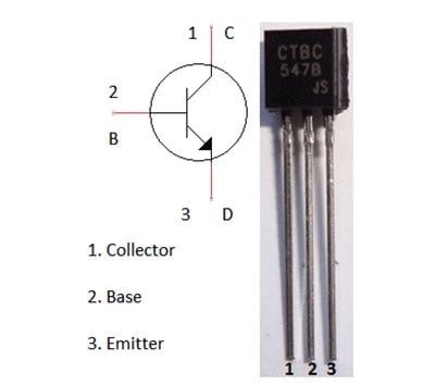
A NPN transistor much acts like a diode if we short the Base (B) and collector (C) of Transistor. In that case B-C acts as Positive terminal and Emitter (E) acts as negative terminal. And if we keep the voltage source constant, then the voltage across the transistor becomes the function of the temperature. For PNP transistor E will be positive terminal and B-C will be negative. Hence by shorting the B and C, we can use transistor as Temperature Detector. Below is the NPN transistor BC547 Pin configuration:
Operating temperature of Transistor BC547 is up to 150 degree C, so it can be perfectly used at high temperature as a Heat Sensor. And we can also make a Fire Alarm out of it.
Comments
Try adjusting the variable
Try adjusting the variable resistor (Pot)
can i get the list of the
can i get the list of the components? please.for our project purpose..
It was a nice and simple
It was a nice and simple project. Such basic projects teaches alot.
can I get that list of
can I get that list of components please for project purpose..thank you
Can I get the list of
Can I get the list of components for this project
Great work! Is it possible to
Great work! Is it possible to sent me the list of components you used so that I can be possible to build it for my school project? It would be grateful if you can! Thanks! :)
Great work! Is it possible to
Great work! Is it possible to sent me the list of components you used so that I can be possible to build it for my school project? It would be grateful if you can! Thanks! :)
transistor
where is the base of the transistor connecting? resistors got only two wires.
is it possible to use any
is it possible to use any transistor as our heat sensor except the one you mentioned above
electronic components
what can i use to test the conditions of the transistor am using.
i really thanks the engrs,
i really thanks the engrs, cuz u ar doing a great job here.... but can i order for ur packages?
instead of light
Hi i liked your project it is simple and good.I am thinking Instead of light why cannot we use piezotwitter
is there any way to power up
is there any way to power up this circuit using a laptop by connecting a USB. urgent please reply.
Yes you can, just connect the
Yes you can, just connect the positive and ground accordingly
Transistor
The picture of the transistor shows "B, C, D", but I think the author means "B, C, E".
Yes Sven it should have been
Yes Sven it should have been B,C,E. It would have been a typo
Can i get the list of
Can i get the list of components please? Really need it a.s.a.p for my lab project purpose..

the project was nice and the cost is less it will be useful to the students