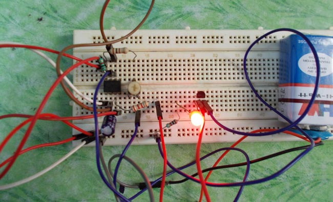
In electronics most commonly failed component is transistor. To test the working of the transistor, one must go through a lot of testing though multimeter. By testing one terminal after another, this consumes a lot of time and also this option is no good for newbies. The transistor testing circuits which are present already are complex to understand and design. In this tutorial we will design a simple 555 TIMER based circuit which will test the working of the transistor in seconds. This circuit is the convenient way to check the working of a transistor for newbies.
The easiest way to check a transistor's working is by testing its switching characteristics. So in this circuit we are going to make transistor switch an LED on and off continuously. The timer here generates clock of 1 Hz and is fed to transistor which is to be tested to drive an LED.
The 555 IC works in free running mode with an adjustable frequency option. With variable frequency one can double check the working of transistor.
Circuit Components
- +9V supply voltage
- 555 IC
- 1KΩ resistors (2 pieces), 2K2Ω resistors
- 10KΩ pot or variable resistor
- 100µF capacitor
- LED
- Transistor (that needed to be tested)
Circuit Diagram and Explanation
The figure shows the circuit diagram of TRANSISTOR TESTER. In this circuit the timer function is to work as a square wave generator and to provide clock for the transistor. This clock is connected to the transistor (transistor to be tested) base. The transistor is provided with a LED to drive. For testing the transistor, its terminals should be connected exactly as give in the table,
|
A |
B |
C |
|
|
NPN |
collector |
base |
emitter |
|
PNP |
emitter |
base |
collector |
Once connected according to the table, power should be turned on and check the following conditions to get the conclusion on transistor working.
The conditions for Transistor working are:
- The LED should be blinking continuously.
- If the pot is adjusted, then LED should be blinking at a different frequency and so both should have relation.
The conditions for Transistor not working are:
- If the LED is off continuously.
- If the LED is on continuously (not blinking).
- Not showing frequency change with pot adjustment.
- Temperature of transistor rising.
The circuit above has current limiting resistors; by this the circuit we will have no problem bearing the short circuit current of a broken transistor. So the circuit can test any transistor without any problem.
The terminal connections should be paid attention during connection, as some transistors have protection diodes causing the LED to turn on continuously and it gives false conclusion.
The capacitor in the circuit can be replaced with a 10uF one for higher frequency of blinking.
Working
Before understanding the working of this circuit, it should be know that a NPN transistor respond to positive voltage only, so to turn on an NPN transistor we should give a voltage greater than 1V. Once the positive voltage is provided at the base, the NPN transistor move from cutoff mode to saturation mode. As for a PNP, to turn on it should be provided with voltage less than or equal to zero. So if the base of a PNP is connected to ground it moves in to conduction.
The clock provide by the timer have positive voltage for half cycle and ground for other half. So the NPN responds to the positive voltage cycle and the PNP responds to the 0V half cycle.
With these triggers the transistor moves to conduction and drives the LED, so the Led blinks.
Comments
transistor tester circuit query
when i change the E and C terminals of transistor, the LED keeps blinking!
i guess it should not happen?
or how can someone know if the terminals of transistor are connected in wrong manner?
Is the Blinking Frequency is
This circuit just test that whether Transistor is faulty or not, it will not tell about the E and C terminal of transistor.
How to convert this to MOSFET tester?
I was wondering how this circuit will be modified to test MOSFETs instead. (IC2N700 for instance).


information given here is very helpfull..