

Technically stepper motor driver circuit is a Decade Binary Counter circuit. The advantage of this circuit is, it can be used to drive stepper motors having 2-10 steps. Before going any further let’s discuss more about the basics of stepper motor.
The name of this motor is given so because the rotation of shaft is in step form which is different from DC or any other motor. In other motors the speed of rotation, the stop angle are not in complete control unless necessary circuit is inserted. This non-control is present because moment of inertia, which is simply a character to start and stop on command without delay. Consider a DC motor, once its powered the speed of motor increases slowly until it catches the rated speed. Now if a load is put on the motor, the speed decreases over the rated and if load is further increased the speed further decreases. Now if the power is turned off the motor does not come to halt immediately as it will have moment of inertia, it stops slowly. Now consider this is a case in a printer the paper outflow does not stop in time, we lose paper every time we start and stop. We need to wait for the motor to pick the speed and due time the paper is lost. This is unacceptable for most of the control systems, so to solve this kind of problems we use stepper motors.
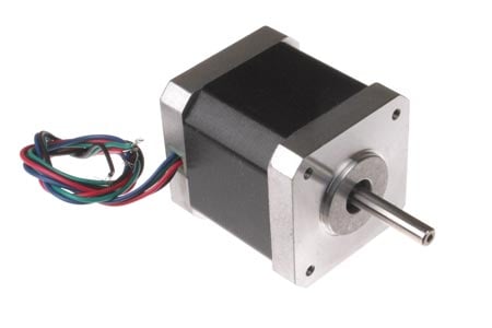
The stepper motor does not work on constant supply. It can only be worked on controlled and ordered power pulses. Before going any further we need to talk about UNIPOLAR and BIPOLAR stepper motorS. As shown in figure in a UNIPOLAR stepper motor we can take the center tapping of both the phase windings for a common ground or for a common power. In first case we can take black and white for a common ground or power. In case 2 black is take for a common. In case3 orange black red yellow all come together for a common ground or power.
In BIPOLAR stepper motor we have phase ends and no center taps and so we will have only four terminals. The driving of this type of stepper motor is different and complex and also the driving circuit cannot be easily designed without a microcontroller.
The circuit which we designed here can only be used for stepper motors of UNIPOLAR type.
The power pulsing of UNIPOLAR stepper motor will be discussed in circuit explanation.
Circuit Components
- +9 to +12 supply voltage
- 555 IC
- 1KΩ, 2K2Ω resistors
- 220KΩ pot or variable resistor
- 1µF capacitor, 100µF capacitor (not a compulsory, connected in parallel to power)
- 2N3904 or 2N2222 (no. of pieces depend on type of stepper if it’s a 2 stage we need 2 if it’s a four stage we need four)
- 1N4007 (no. of diodes is equal to no. of transistors)
- CD4017 IC, .
Stepper Motor Driver Circuit Diagram and Explanation

The figure shows the circuit diagram of two stage stepper motor driver. Now as shown in the circuit diagram the 555 circuit here is to generate clock or the square wave. The frequency of clock generation in this case cannot be kept constant so we need to get variable speed for the stepper motor. To get this variable speed a pot or a preset is paced in series with 1K resistor in branch between 6th and 7th pin. As the pot is varied the resistance in the branch changes and so the frequency of clock generated by 555.
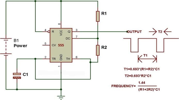
In the figure the important thing is only the third formula. You can see that the frequency is inversely related to R2 (which is 1K+220k POT in the circuit). So if R2 increases the frequency decreases. And so if the pot is adjusted to increase the resistance in the branch the frequency of clock decreases.
The clock generated by 555 timer is fed to DECADE BINARY counter. Now the decade binary counter counts the number of pulses fed at the clock and lets the corresponding pin output go high. For example if the event count is 2 then Q1 pin of counter will be high and if 6 is count the pin Q5 will be high. This is similar to binary counter however the counting will be in decimal (ie., 1 2 3 4 __ 9) so if the count is seven only Q6 pin will be high. In binary counter Q0,Q1 and Q2 (1+2+4) pins will be high. These outputs are fed to transistor to drive the stepper motor in orderly way.

In figure we are seeing a four stage stepper motor driver circuit very similar to the two stage one. In this circuit, it can be observed that the RESET connected to Q2 before is now moved to Q4 and the opened Q2 and Q3 pins are connected to another two transistors to get a four pulse driving set to run the four stage stepper motor. So it is clear that we can drive up to ten stage stepper motor. However one should move the RESET pin up in order so to fit in driving transistors in place.
The diodes placed here are to protect the transistors from inductive spiking of the stepper motor winding. If these are not placed one might risk blowing the transistors. Greater the frequency of pulses,greater the chance of blow up without diodes.
Working of Stepper Motor Driver
For better understanding of step rotation of stepper motor we are considering a four stage stepper motor as shown in figure.
Now consider, for an example, all coils are magnetized at a time. The rotor experiences forces of equal magnitude from all around it and so it does not move. Because all are of equal magnitude and are expressing opposite direction. Now if the coil D only magnetized, the teeth 1 on rotor experiences an attractive force towards +D and teeth 5 of rotor experiences a repulsive force opposing the –D, theses two forces are represents an additive force clock wise. So the rotor moves to complete a step. After that it stops for the next coil to energize to complete next step. This goes on until the four steps are complete. For the rotor to rotate this cycle of pulsing must be going on.
As explained before, the preset is set to a value for a certain frequency of pulses. This clock is fed to the decade counter to get regular outputs from it. The outputs from decade counter are given to transistors to drive the high power coils of stepper motor in sequential order. The tricky part is, once a sequence is complete say 1, 2, 3, 4 the stepper motor completes four steps and so it is ready to start again however the counter has a capacity to go for 10 and so it goes on without interruption. If this happens the stepper motor must wait till the counter completes its cycle of 10 which is not acceptable. This is regulated by connecting RESET to Q4 so when counter goes for five count it resets itself and starts from one, this starts the sequence of stepper.
So this is how the stepper continuous it’s stepping and so the rotation happens. For a two stage the RESET pin must be connected to Q2 for the counter to resets itself in the third pulse. This way one can adjust the circuit to drive ten step stepper motor.
Comments
motors diagrams and working principles
It is well explained and helpful
Stepper motor driver cct.
How do you reverse step motor rotation direction with this circuit ?
Reverse it
Lionel, to reverse the direction you have to reverse the count, at present it counts UP so you need to make it count DOWN so a different counter chip would be needed, one where the count direction can be switched, search for UP DOWN COUNTER IC in Mr Google.
Peter
Parts List
Your Part List shows the need for a IN4047 diode. Is this a typo? Shouldn't it match the schematic and say IN4007? I looked up that part number, surprisingly, it exists, though not a diode. Digi-Key carries it and it's not cheap($52 US), I would hate to have a newbie order four of them to finish this circuit. All that aside, thanks for putting this together.
Circuitry for Bipolar Stepper Motor
Hello,
I'm building an astro tracker and i'm using this:
banggood.com/JKM-42-Linear-Stepper-Motor-Trapezoidal-Screw-320MM-0_32NM-p-933434.html
I read your article and I saw that it's complicated... so do i absolutely have to use an arduino board?
Or would you have something i could use with a couple of 555 timers... and a variable resistor?
Thanks,
Reuben
You can do it without Arduino
You can do it without Arduino as we did with 555 timer.
very nice video....& nice
very nice video....& nice diagram in simple..thanks a lot
Stopping the counter after one rotation
Can you set up the circuit to stop after 4 stages or one rotation?
The type of motor to be used.
What type of stepper motor should I use? 4-phase, bipolar or unipolar? The one which is simpler to construct and use?
control system
hi! can i ask if that motor can reverse also by calibrating that vr!? or it moving by one direction only?
YES! it can also rotate in
YES! it can also rotate in reverse direction
stepper motor drive circuit
Can you provide me with the schematic thank you . Alberto
Awesome simple stepper circuit when programability isn't needed
I wish it was available in a pre-wired circuit-board where we could just swap out resistors. Frankly speaking, I'm surprised that doesn't exist as it seems like it would be a good seller.
Using a ULN2003 board with the above
Great tutorial. My stepper motors come with a little ULN2003 interface board. Looking at the specs for the ULN2003 I am guessing that I can use it in place of the output transistors and diodes in your schematic (i.e. hook the output pins of the CD4017 to the input pins of the ULN2003.) Is it that simple or would I need other components?
LEDs indicate correct sequence but motor just clicks
Hi, I constructed the circuit as per your instructions above, only substituting a ULN2003 driver board that came with the 28byj-48 motor for the four output diodes in the schematic. The LEDs on the driver board seem to indicate that the driver lines are being energized in the correct sequence, but the motor doesn't turn, it just clicks or vibrates. I read somewhere that the sequence to cleanly rotate the motor should be A-AB-B-BC-C-CD-D-DA, so I modified your circuit to use 8 of the decade counter outputs to generate the above sequence, by using each odd numbered counter output to drive two motor driver lines, and with diodes to prevent unwanted shorts. Again the driver board LEDs show what appears to be the correct sequence, but the motor still just vibrates.
I know that the motor is not defective as I have tested it with an Arduino, using very basic I/O output (i.e. not using any stepper library code) to generate the above sequence and it works just fine. In this configuration the motor is powered seperately by the same 5V power supply that I'm using to power the decade counter circuit, the Arduino itself is powered by USB.
I was really hoping to eliminate the Arduino, as my requirement is for very simple constant slow rotation and the Arduino seems to be overkill for that purpose.
Do you or anyone else have any idea why the motor isn't rotating?
Stepper motor not turning
Update: I found the cause of the problem, and it is exactly what many people have said online - incorrect motor wiring. I was connecting the output lines in the wrong order(IN1-IN4). When I reversed the order (IN4-IN1) the motor rotates as expected, and without the need for the extra 'dual' coil activations.

Nice one