

A Zero Crossing Detector Circuit is a useful application of Op-amp as Comparator. It is used to track the changing in the sine waveform from positive to negative or vice versa while it crosses Zero voltage. It can also be used as a Square Wave Generator. Zero Crossing Detector has many applications like time marker generator, phase meter, frequency counter etc. A Zero Crossing Detector can be designed in many ways like using transistor, using op-amp or using optocoupler IC. In this article we will use Op-amp to build a Zero Crossing Detector Circuit and as mentioned previously, Op-amp will work as comparator here.
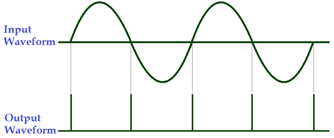
The ideal waveform for Zero Crossing Detector is given below:
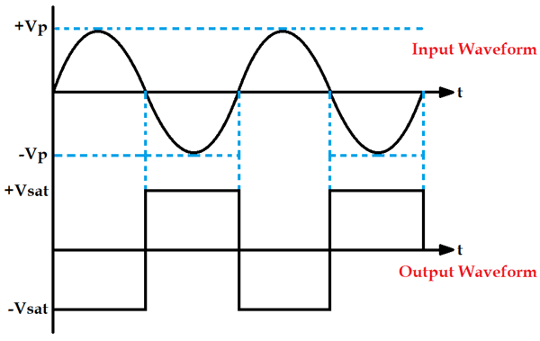
It can be seen in the above waveform that whenever the sine wave crosses zero, the output of the Op-amp will shift either from negative to positive or from positive to negative. It shifts negative to positive when sine wave crosses positive to negative and vice versa. This is how a Zero Crossing Detector detects when the waveform is crossing zero every time. As you can observe that the output waveform is a square wave, so a Zero Crossing Detector is also called a Square wave Generator Circuit.
To learn more about op-amps, check other op-amp circuits.
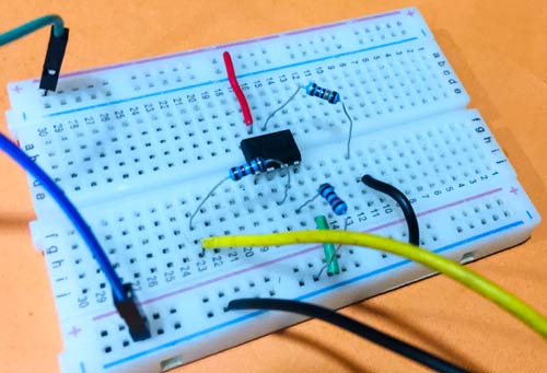
Material Required for Zero Crossing Detector Circuit Demonstration
- Op-amp IC (LM741)
- Transformer (230V-to-12V)
- 9V supply
- Resistor (10k – 3nos)
- Breadboard
- Connecting Wires
- Oscilloscope
Zero Crossing Detector Circuit Diagram

230v Supply is given to a 12-0-12V transformer, and its phase output is connected to the 2nd Pin of the Op-amp and neutral is short with the ground of the battery. The positive terminal of the battery is connected to the 7th pin (Vcc) of the op-amp.
Working of Zero Crossing Detector Circuit
In a Zero Crossing Detector Circuit, the non-inverting terminal of the Op-amp is connected with the ground as a reference voltage and a sine wave input (Vin) is fed to the inverting terminal of the op-amp, as you can see in the circuit diagram. This input voltage is then compared with the reference voltage. Any general purpose op-amp IC can be used here, we have used op-amp IC LM741.
Now, when you consider the positive half cycle of the sine wave input. We know that, when the voltage at the non-inverting end is less than the voltage at inverting end, the output of the Op-amp output is Low or of negative saturation. Hence, we will receive a negative voltage waveform.
Then in negative half cycle of the sine wave, the voltage at the non-inverting end (reference voltage) becomes greater than the voltage at inverting end (input voltage), so the output of the Op-amp becomes High or of positive saturation. Hence, we will receive a positive voltage waveform, as you can see in the below image:
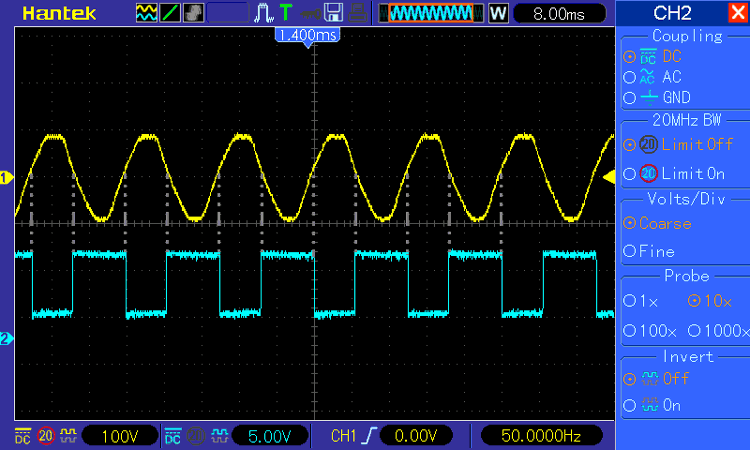
Thus it is clear that this circuit can detect the Zero crossing of waveform by switching its output from negative to positive or from negative to positive.
Zero Crossing Detector Using Optocoupler
As we have already mentioned that there are many ways to design a Zero Crossing Detector. Here, in the below circuit we are using an opto-coupler for the same. By observing the output waveform you can see that the output waveform is getting HIGH only when the input AC wave crosses zero every time.
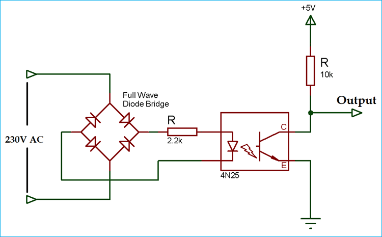
Below is the output waveform of the Zero Crossing Detector Circuit using Optocoupler:
The zero-crossing pulse output is getting HIGH at 0⁰, 180⁰ and 360⁰ or we can say after every 180⁰.

Hello Pankaj,
In the 2nd sample circuit, Zero Crossing Detector Using Optocoupler, is there supposed to be a transformer between the 230VAC input and the Bridge Rectifier? Not sure is possible to apply 230V to the 4N25 with only a 2.2k resistor.
Thank you!
Agustin