
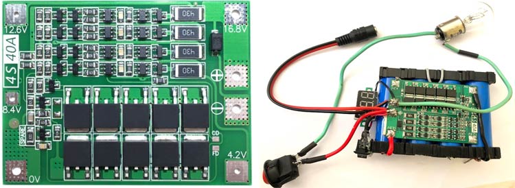
In this article, we are going to test a 4s 40A BMS. We will first design a 4s battery pack and then attach the BMS with the battery pack to perform all the features of the BMS. Due to the high energy density of Li-ion cells and their rechargeable capabilities, Li-ion cells are getting extremely common to make battery packs for different applications. But we need to connect a Li-ion cell in order to protect the circuit from getting damaged or degrading the life of the cell, we need to connect with a BMS. In this article we will be designing a simple 4S battery pack and connecting it with a 4S 40 Amps BMS circuit to make a robust battery pack. Furthermore, we will test all the protection features of the BMS.
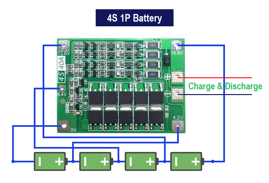
This is a 4S 1P battery pack, but if we want, we can connect higher-capacity cells or cells in parallel. Therefore, we can use the same BMS to make a 4s 2P battery pack or a 4s 3P battery pack, etc.
This BMS comes in 3 variants, the standard version, the enhanced version, and the balanced version.
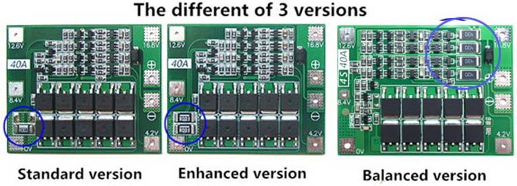
We will be looking at the Balanced version. The standard version and enhanced version are almost similar with just a difference of 1 passive component, these variants are not capable of actively balancing the cells, whereas the balanced version has circuitry for balancing the cells. The balanced version has an extra IC and resistors which are capable of load balancing.
The connection for all the versions with the cells is exactly the same. The connection of the BMS module with the cell will be shown later in the article.
BMS module Features
The 4s 40Amp BMS has advanced features required to improve the lifecycle of the battery pack. The protection features available in the 4s 40A Battery Management System are:
- Cell Balancing
- Overvoltage protection
- Short circuit protection
- Undervoltage protection
Designing the Battery Pack!!
To test the feature of the BMS we will require to connect all the cells in series to make a 4s battery and connect the BMS with this 4S battery.
For making the battery pack we require a 4S 40A BMS module, 4 Li-ion cells, nickel strip, DC female barrel jack, and cell connecting brackets. Apart from these, we will also connect a voltmeter, and a bulb to show the pack in operations, which will be connected through a switch.
BMS connection with the Battery Pack
The BMS module has a neat layout with markings for connecting the BMS with different locations in the battery pack. The image below shows how we will connect the cell with BMS.
|
Markings on the BMS |
Connection with the BMS |
|
- |
Negative Terminal Connection for the battery pack for charging and connecting the load. |
|
+ |
positive Terminal Connection for the battery pack for charging and connecting the load |
|
0 |
Negative terminal of the 1st cell |
|
4.2 |
Positive terminal of the 1st cell |
|
8.4 |
Positive terminal of the 2nd cell |
|
12.6 |
Positive terminal of the 3rd cell |
|
16.8 |
Positive terminal of the 4th cell |
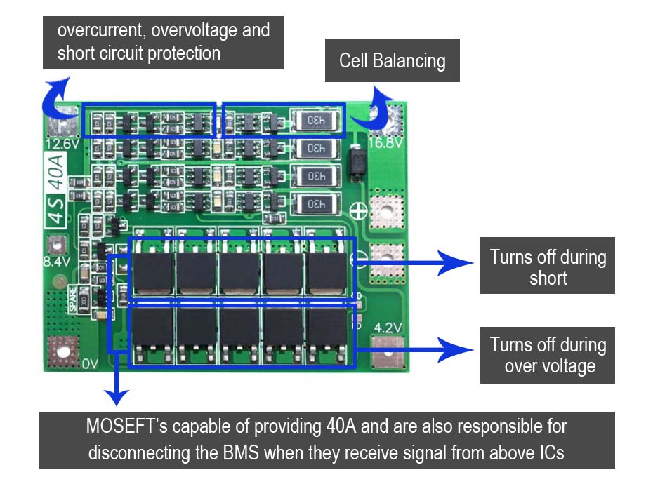
4S 40Amp BMS Module
The 4S 40A BMS Module has 2 ICs, DW01-A, and BB3A that are responsible for the protection and balancing respectively. The section of BMS for protection and balancing is marked in the image below.
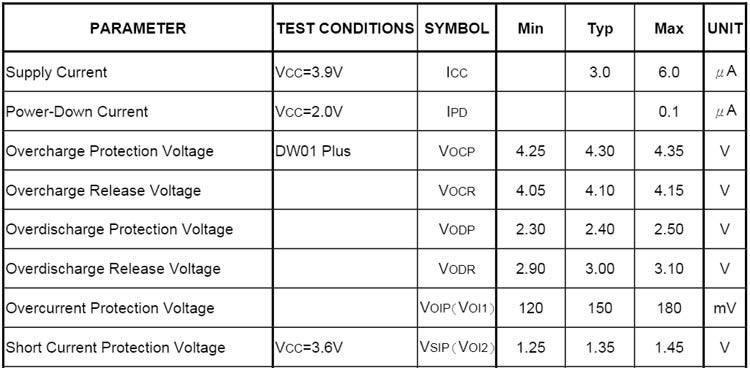
Protection Parameter for each individual Cells
The protection feature of the battery management system depends upon the electrical characteristics of the DW01 IC. The protection parameters followed by the IC are given in the table below.
Testing features of the BMS
The 4S 40A has features such as over-voltage protection, over-current protection, short-circuit protection, over-discharge protection, and cell balancing. More details about these features are given in the description below.
Testing Overcharge Protection
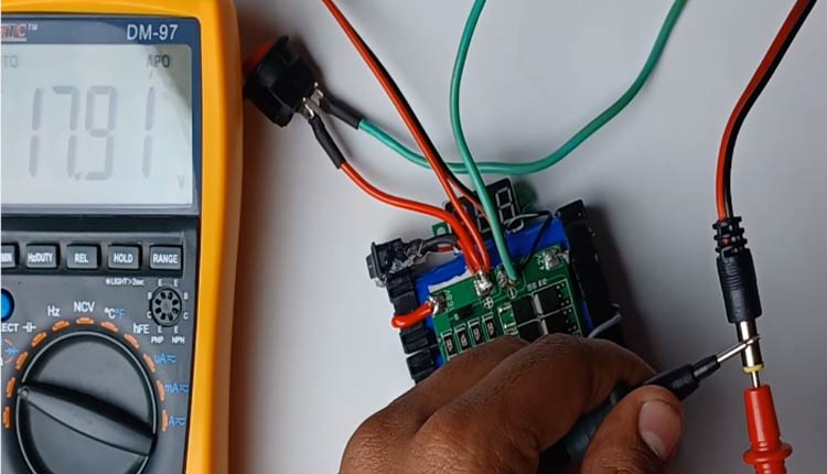
To test the over-charge feature of the battery pack, we first have to charge the battery pack so that the cell charges over the prescribed limit, i.e. the overcharge protection voltage of 4.35V. Once the cell has reached VOCP, the battery pack stops charging any further. The charger I have used is a constant voltage charger that provides 18 volts. As seen in the image below, the voltage from the charger is 17.91 volts.
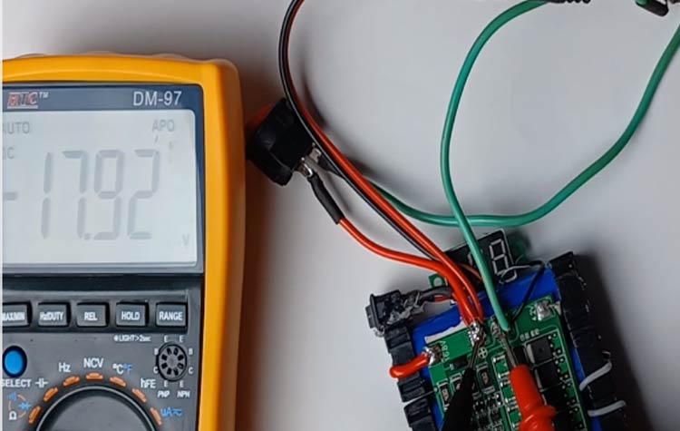
The image below shows that the voltage at the BMS when the charger is connected is 17.92V which means that the charger is connected with the BMS.
The image below shows that the voltage across the positive and negative terminals of the battery is 16.29 volts.
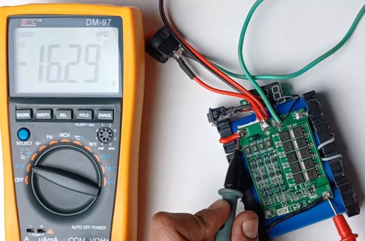
The voltage from the charger is 17.91V while the voltage across the positive and negative terminal of the battery is 16.29 Volt (it’s having a negative voltage as I have connected the probe of the multimeter in opposite terminals). The difference in the voltage output is caused because the BMS has stopped the charger from supplying the power to the cells by disconnecting the 4s battery from the BMS output terminal, thus it shows that the overvoltage protection of the BMS does work.
Testing Undervoltage Protection
To test the undervoltage protection, we drained the battery using a Nichrome wire. The IC DW01 is responsible for protecting each cell from undervoltage. So, whenever the voltage of any cell drops below 2.4V, i.e. the over-discharge protection voltage, the undervoltage protection kicks in and the BMS disconnects the load. And until the cell is recharged and the cell is charged till over-discharge protection voltage, i.e. above 3V, the BMS doesn’t allow any load to draw power thus maintaining the life of the cell.
Cell Balancing
The cell balancing is possible due to the BB3A IC. When the out pin from pin 6 of BB3A gives a high signal to the gate of an enhancement type N-MOSFET, the MOSFET connects a low resistance path through this 480-ohm resistance which acts as a load resistor and starts depleting the battery.
The rate of discharge is:
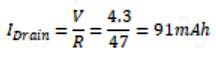
To show how it works, we used a multimeter to check the connectivity between the Drain and Source of the MOSFET. When the balancing was not working, the N-channel MOSFETS were in the closed condition and the continuity test proved that the MOSFETS were turned off and when the cells balancing turned on the MOSFET let the current flow through the Drain and Source thus showing results in the continuity test.
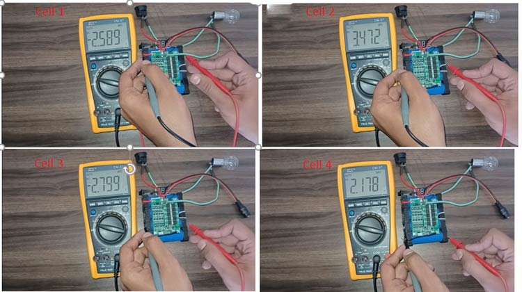
The below set of images show how the cells were at different potential when the battery was not charging.
After the battery pack was charged, the cell balancing started working.
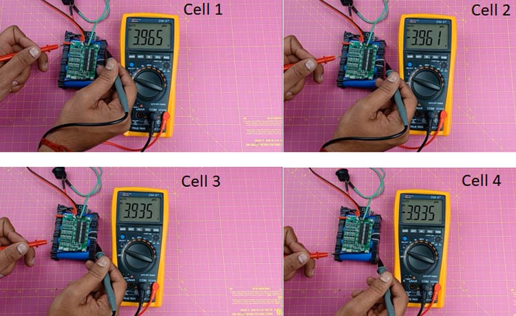
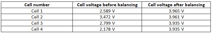
As you can see from the 1st image, all the cells were at different potentials whereas after charging the battery pack, all the cells were at a similar potential. The comparison of the cell voltages before and after charging and balancing is shown in the table below-
Short circuit test
To show the short circuit test, I turned on the bulb and the volt-meter, and as soon as I shorted the BMS positive and negative terminal, both the bulb and the voltmeter stopped working, and until I turn off all the switches and disconnected all the loads for few mill-seconds, the BMS didn’t turn back on.
After turning off all the connections, and then turning on the devices, it started working again proving that the BMS is protecting the battery pack from a short circuit.
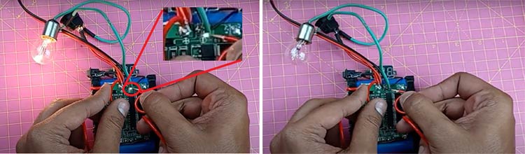
The above-left image shows a spark coming off from the negative terminal to the wire which shows a short circuit, as soon as the short circuit took place, the BMS disconnected all the load from the battery pack.
Conclusion
The 4S 40 Amp BMS is a simple to use module having advanced features that can extend the battery pack’s life. Apart from extending the life, it is also protecting the cells and the whole battery pack from causing fire or experiencing the thermal runaway thus protecting the battery pack and surroundings from a potential fire hazard.
I hope you enjoyed the article, if you have any queries, kindly write it in the comments below.
Comments
What is maximum charging voltage for this BMS ?
16.8V

Hello Sir,
Nice Video, just want to ask a couple of question.
More power to your web site and projects.
Edgar A . From Philippines.