
The ATtiny family is a series of one of the smallest microcontrollers in the AVR market. These microcontrollers are capable of utilizing many of the libraries available on the Arduino platform. The ATtiny85 microcontroller chip is 8-pin, 8-bit, AVR microcontroller. Its small size and low power consumption make it a great match for portable projects with small footprints and low power requirements. But getting your code onto the chip can be a little bit of a challenge as it doesn’t have any USB interface like microcontroller boards.
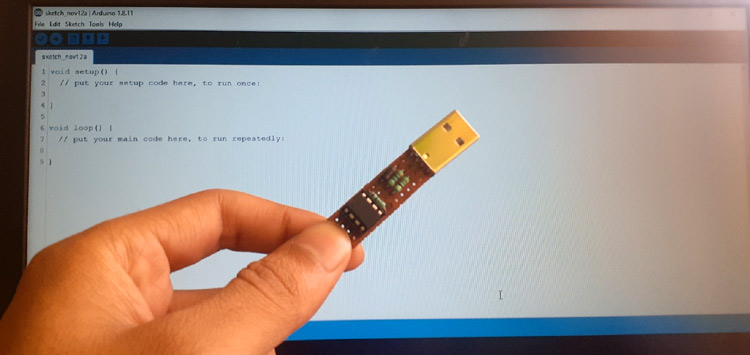
In our previous tutorial, we programmed the ATtiny85 using Arduino Uno. But connecting Attiny85 to Arduino and using Arduino as ISP can be difficult and time-consuming. So in this tutorial, we are going to build an ATtiny85 Programming board, so that we can directly plugin and program it like other microcontroller boards.
Components Required to Program ATtiny85 through USB
- Arduino UNO (Only for the first time while uploading bootloader)
- ATtiny85 IC
- USB A-type Plug Male
- 3 Resistors (2×47Ω & 1×1kΩ)
- 3 Diodes (2×Zener Diode & 1×IN5819 Diode )
- 8-Pin IC Base
- Breadboard
- Jumper Wires
ATtiny85 Microcontroller IC – Introduction
Atmel's ATtiny85 is a high performance, low power 8-bit microcontroller based on Advanced RISC Architecture. This microcontroller chip features 8KB ISP flash memory, 512B EEPROM, 512-Byte SRAM, 6 general-purpose I/O lines, 32 general purpose working registers, one 8-bit timer/counter with compare modes, one 8-bit high-speed timer/counter, USI, internal and external Interrupts, 4-channel 10-bit A/D converter, programmable watchdog timer with internal oscillator, three software selectable power saving modes, and debugWIRE for on-chip debugging. ATtiny85 Pinout is given below:
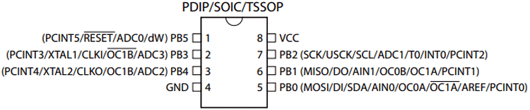
Most of the I/O pins of the chip have more than one function. ATtiny85 pin description for each pin is given in below table:
|
Pin No. |
Pin Name |
Pin Description |
|
1 |
PB5(PCINT5/ADC0/dW) |
PCINT5: Pin Change Interrupt 0, Source5 RESET: Reset Pin ADC0: ADC Input Channel 0 dW: debug WIRE I/O |
|
2 |
PB3(PCINT3/XTAL1/CLKI/ADC3) |
PCINT3: Pin Change Interrupt 0, Source3 XTAL1: Crystal Oscillator Pin1 CLKI: External Clock Input ADC3: ADC Input Channel 3 |
|
3 |
PB4 (PCINT4/XTAL2/CLKO/OC1B/ADC2) |
PCINT4: Pin Change Interrupt 0, Source 4 XTAL2: Crystal Oscillator Pin 2 CLKO: System Clock Output OC1B: Timer/Counter1 Compare Match B Output ADC2: ADC Input Channel 2 |
|
4 |
GND |
Ground Pin |
|
5 |
PB0(MOSI/DI/SDA/AIN0/OC0A/AREF/ PCINT0) |
MOSI: SPI Master Data Output / Slave Data Input DI: USI Data Input (Three Wire Mode) SDA: USI Data Input (Two Wire Mode) AIN0: Analog Comparator, Positive Input OC0A: Timer/Counter0 Compare Match A output AREF: External Analog Reference PCINT0: Pin Change Interrupt 0, Source 0 |
|
6 |
PB1(MISO/D0/AIN1/OC0B/OC1A/ PCINT1) |
MISO: SPI Master Data Input / Slave Data Output DO: USI Data Output (Three Wire Mode) AIN1: Analog Comparator, Negative Input OC0B: Timer/Counter0 Compare Match B Output OC1A: Timer/Counter1 Compare Match A Output PCINT1: Pin Change Interrupt 0, Source 1 |
|
7 |
PB2(SCK/USCK/SCL/ADC1/T0/INT0/ PCINT2) |
SCK: Serial Clock Input USCK: USI Clock (Three Wire Mode) SCL: USI Clock (Two Wire Mode) ADC1: ADC Input Channel 1 T0: Timer/Counter0 Clock Source INT0: External Interrupt 0 Input PCINT2: Pin Change Interrupt 0, Source 2 |
|
8 |
VCC |
Supply Voltage Pin |
Flashing Boot-loader on ATtiny85 Using Arduino Uno
For programming the ATtiny85 without Arduino, we would first have to upload a bootloader into it using an Arduino UNO board, this is a one-time process and after this is done, we will not be needing the UNO board again. Boot-loader is a special program that runs in the microcontroller that has to be programmed. One of the most convenient ways to load your program data onto the microcontroller is through a boot-loader. Boot-loader sits on the MCU and performs the incoming instructions, and then writes new program information to the microcontroller’s memory. Flashing a boot-loader on a microcontroller removes the need for special external hardware (Programmer Boards) to program the microcontroller and you will be able to program it directly using a USB connection. The Digispark ATtiny85 board runs the “micronucleus tiny85” boot-loader, originally written by Bluebie. The boot-loader is the code that is pre-programmed on Digispark and allows it to act as a USB device so that it can be programmed by the Arduino IDE. We are also going to flash the same digispark attiny85 bootloader on ATtiny85.
A step by step guide to flash bootloader onto ATtiny85 using Arduino Uno and Arduino IDE is given below:
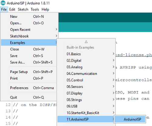
Step1: Configuring Arduino Uno as an ISP:
Since the ATtiny85 is just a microcontroller, it requires an ISP (In-System Programming) to be programmed. So to program the ATtiny85, we need to first configure Arduino Uno as ISP to act as a programmer for the ATtiny85. For that, connect the Arduino Uno to Laptop and open the Arduino IDE. After that, navigate to File > Example > ArduinoISP and upload the Arduino ISP code.
Step 2: Circuit Diagram for Flashing Boot-loader on ATtiny85:
The complete schematic for Flashing Boot-loader on ATtiny85 is given below:
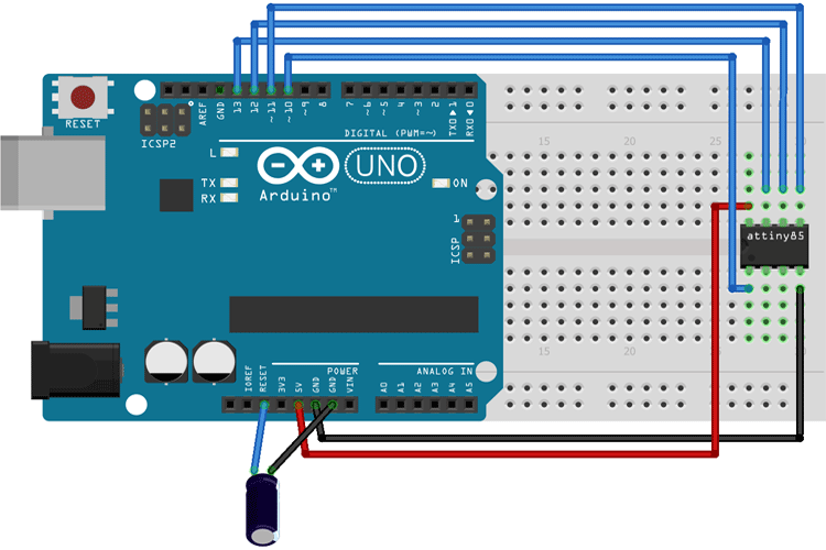
A 10 µf capacitor is connected between the Reset and GND pin of Arduino. The complete connections are given in the below table:
|
ATtiny85 Pin |
Arduino Uno Pin |
|
Vcc |
5V |
|
GND |
GND |
|
Pin 2 |
13 |
|
Pin 1 |
12 |
|
Pin 0 |
11 |
|
Reset |
10 |
Now plug-in the Arduino Uno to the laptop and open Arduino IDE. Find what COM port the Uno is connected to. In my case, it's COM5.
After this, download the ATtiny85 Boot-loader files from the given link. Open "Burn_AT85_bootloader.bat" and change the COM port number "PCOM5" with whatever COM port number your Uno is connected to. Save the changes before exiting.
Now move the edited "Burn_AT85_bootloader.bat" and "ATtiny85.hex" files into the Arduino IDE root folder (C:\Program Files (x86)\Arduino).
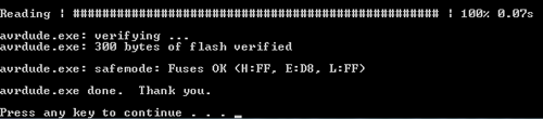
After that, right-click on "Burn_AT85_bootloader.bat" and select "Run as Admin". It takes approx 5 to 6 seconds to flash the boot-loader. If all went well, you should receive this message "AVRdude done. Thank you. Press any key to continue...".
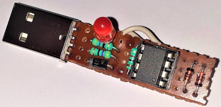
With this, the Boot-loader is successfully installed onto the ATtiny85 Chip. Now it’s time to connect USB with ATtiny85 so that we can program it directly. The circuit diagram for programming ATtiny85 through USB is given below:
Circuit Diagram for ATtiny Programmer
The schematic is taken from the Digispark ATtiny85 board schematic but as we aim to build a programmer for ATtiny85, we are only connecting Male USB Plug with ATtiny85.

The R3 is a pull-up resistor that is connected between Vcc and PB3 pins of IC while the Zener Diodes (D1-D2) are added for total USB interface protection. After soldering all the components on the perf board, it will look something like below:
Installing Digispark Drivers
To program the ATtiny85 using USB, you must have Digispark Drivers installed on your laptop, if you don’t have them, you can download it using the link given above. Then, extract the zip file and double click on the “DPinst64.exe” application to install the drivers.
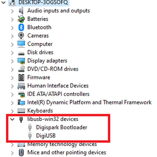
Once the drivers are successfully installed, Plug in your ATtiny85 board to the laptop. Now go to Device Manager on your Windows and the ATtiny85 device will be listed under “libusb-win32 devices” as “Digispark Bootloader”. If you can’t find ‘libusb-win32 devices’ on the device manager, then go to View and click on ‘Show hidden Devices.’

Setting up Arduino IDE to Program ATttiny85
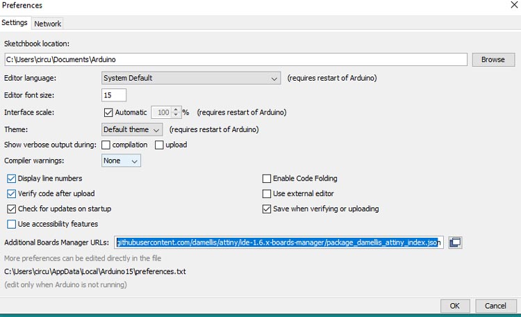
To program the ATtiny85 Board with Arduino IDE, first, we need to add the Digispark board Support to Arduino IDE. For that, go to File > Preferences and add the below link in the Additional Boards Manager URLs and click ‘OK.’
http://digistump.com/package_digistump_index.json
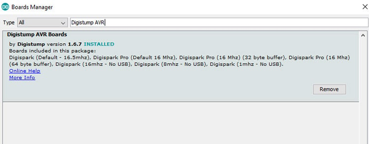
After that, go to tools > Board > Board Manager and search for ‘Digistump AVR’ and install the latest version.
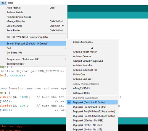
After installing it, now you would be able to see a new entry in the Board menu titled 'Digispark'.
Now, go to file > Examples > Basics and open the Blink example.
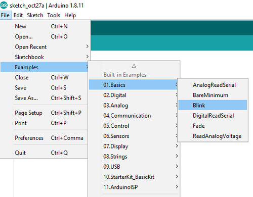
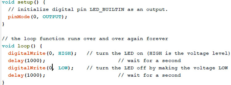
Change the pin number on there from LED_BUILTIN to 0.
Now go back to Tools -> Board and select the “Digispark (Default – 16mhz)” board. Then click on the upload button in Arduino IDE.
Note: Connect the ATtiny85 board to the computer, only when the Arduino IDE displays a message saying “Plugin device now”.
Once the code is uploaded, the LED connected to ATtiny85 should start blinking.
This is how you can build your own ATtiny85 Arduino Programming board. A working video of the same is given below. If you have any questions, leave them in the comment section. For any other technical questions, you can also start a discussion on our forums.
Comments
Original .bat file is fixed. Thank you. Disregard my comments.
Hey, how can i contact you? :) Everything is working, but i need to change one pin in my project, is it possible that you can share your source files? :)
Hi!
Interesting projekt.
What is the value of the zenerdiod.
I can't find it in the text.
Regards
/Peter
The attiny85 circuit is not responding. even USB is not coming in the device manager.
Please help.
Probably because diode D2 is reversed in the schematic. Flip it over and it should work.
The schottky diode D2 in your schematic is reversed. This will never work. USB power will not reach the ATTiny85.

The .bat file is looking for file with name AT85_Bootloader.hex. To burn the bootloader you have to change not only the number of the port as explained above. You have to change the name of the .hex file from ATtiny85.hex to AT85_Bootloader.hex, too. The best will be the autor to fix original files.