

What is Resistor?
Resistors are current limiting devices with are used abundantly in electronics circuits and products. It is a passive component which provides resistance when current flow through it. There are many different types of resistors. Resistance is measured in Ohm with a sign of Ω.
What are Pull-up and Pull-Down Resistor and Why we need them?
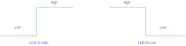
If we consider a digital circuit, the pins are always be either 0 or 1. In some cases, we need to change the state from 0 to 1 or from 1 to 0. In either case, we need to hold the digital pin either 0 and then change the state to 1 or we need to hold it 0 and then change to 1. In both cases, we need to make the digital pin either ‘High’ or ‘Low’ but it cannot be left floating.
So, in each case, the state gets changed as shown below.
Now, if we replace the High and Low value with the actual voltage value then the High will be the logic level HIGH (lets say 5V) and Low will be the ground or 0v.
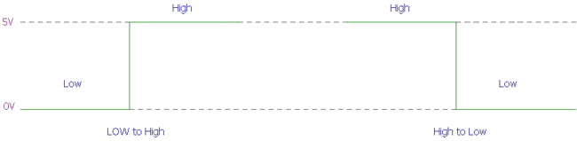
A Pull-up resistor is used to make the default state of the digital pin as High or to the logic level (in the above image it is 5V) and a Pull-Down resistor does exactly opposite, it makes the default state of the digital pin as Low (0V).
But why we need those resistors instead we could connect the digital logic pins directly to the Logic level voltage or with the ground like the below image?
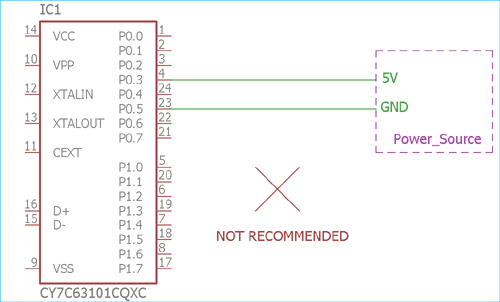
Well, we could not do this. As digital circuit works in low current, connecting the logic pins directly to the supply voltage or the ground is not a good choice. As direct connection eventually increase current flow just like the short circuit and could damage the sensitive logic circuit which is not advisable. To control the current flow, we need those pull-down or pull up resistors. A pull-up resistor allow controlled current flow from supply voltage source to the digital input pins, where the pull-down resistors could effectively control current flow from digital pins to the ground. At the same time both resistors, pull-down and pull-up resistors hold the digital state either Low or High.
Where and How to use Pull-up and Pull-down resistors
By referencing the above microcontroller image, where the digital logic pins are shorted with the ground and VCC, we could change the connection using pull-up and pull-down resistors.
Suppose, we need a default logic state and want to change the state by some interaction or external peripherals, we use a pull-up or pull-down resistors.
Pull-up Resistors
If we need the high state as default and want to change the state to Low by some external interaction we can use the Pull-up resistor like the image below-
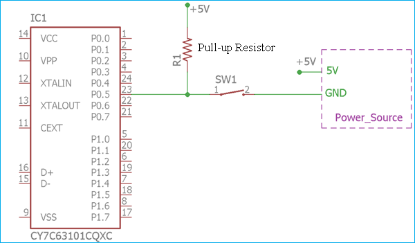
The digital logic input pin P0.5 can be toggled from logic 1 or High to the logic 0 or Low using the switch SW1. The R1 resistor is acting as a pull-up resistor. It is connected with the logic voltage from the supply source of 5V. So, when the switch is not being pressed, the logical input pin has always a default voltage of 5V or the pin is always High until the switch is pressed and the pin is shorted to ground making it logic Low.
However, as we stated that the pin cannot be directly shorted to the ground or Vcc as this will eventually make the circuit damaged due to short circuit condition, but in this case, it is again getting shorted to the ground using the closed switch. But, look carefully, It is not actually getting shorted. Because, as per the ohms law, due to the pull-up resistance, a small amount of current will flow from the source to the resistors and the switch and then reach the ground.
If we do not use this pull-up resistor, the output will get directly shorted to the ground when the switch is being pressed, on the other hand, when the switch will be open the logic level pin will be floated and could make some undesirable result.
Pull Down Resistor
The same thing is true for the Pull-down resistor. Consider the below connection where pull-down resistor is shown with the connection-
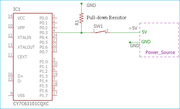
In the above image, exactly opposite thing is happening. The pull-down resistor R1 which is connected with the ground or 0V. Thus making the digital logic level pin P0.3 as default 0 until the switch is pressed and the logic level pin became high. In such case, the small amount of current flows from the 5V source to the ground using the closed switch and Pull-down resistor, hence preventing the logic level pin to getting shorted with the 5V source.
So, for various logic level circuits, we can use Pull-up and Pull-down resistors. It is most common in various embedded hardware, one wire protocol system, peripheral connections in a microchip, Raspberry Pi, Arduino and various embedded sectors as well as for the CMOS and TTL inputs.

Calculating the Actual Values for Pull-up and Pull-down Resistors
Now, as we know how to use the Pull-up and Pull-down resistor, the question is what will be the value of those resistors? Although, in many digital logic level circuits we can see pull-up or pull-down resistors ranging from 2k to 4.7k. But what will be the actual value?
To understand this, we need to know what is the logic voltage? How much voltage is referred as Logic low and How much is referred as Logic High?
For various logic levels, various microcontrollers use a different range for the logic high and logic low.
If we consider a Transistor-Transistor Logic (TTL) Level input, below graph will show the minimum logic voltage for the Logic high determination and maximum logic voltage for detecting the logic as 0 or Low.
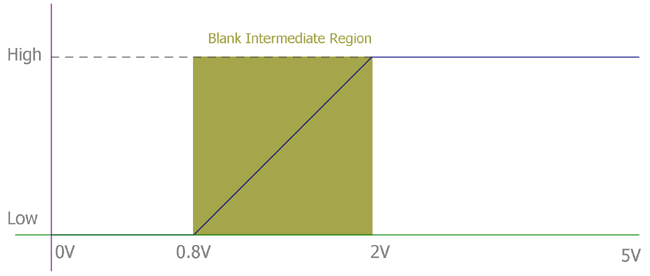
As we can see, that for the TTL logic, the maximum voltage for logic 0 is 0.8V. So, if we provide less than 0.8V the logic level will be accepted as 0. On the other hand, if we provide more than 2V to the maximum 5.25V the logic will be accepted as High. But at the 0.8V to the 2V, it is a blank region, at that voltage it cannot be guaranteed that the logic will be accepted as High or Low. So, for safe side, In TTL architecture, we accept 0V to 0.8V as Low and 2V to the 5V as High, which is guaranteed that Low and High will be recognized by the logic chips at that marginal voltage.
To determine the value, the formula is simple Ohms law. As per the ohms law, the formula is
V = I x R
R = V/I
In case of the Pull-up resistor, the V will be the source voltage – minimum voltage accepted as High.
And the current will be the maximum current sunk by the logic pins.
So,
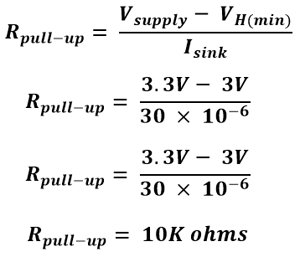
Rpull-up = (Vsupply – VH(min)) / Isink
Where Vsupply is the supply voltage, VH(min) is minimum accepted voltage as High, and Isink is the maximum current sinked by the digital pin.
The same thing is applicable to the Pull-down resistor. But the formula has a slight change.
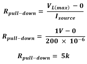
Rpull-up = (VL(max) – 0) / Isource
Where (VL(max) the maximum voltage is accepted as logic Low, and Isource is the maximum current sourced by the digital pin.
Practical Example
Suppose we have a logic circuit where the Supply source is 3.3V and the acceptable logic high voltage is 3V, and we could sink a current maximum of 30uA, then we can choose the pull-up resistor using the formula like this way-
Now, If we consider the same example stated above, where the circuit accepts 1V as the maximum logic Low voltage and could source up to 200uA of current then the Pull-down resistor will be,
More about Pull-Up and Pull-Down Resistors
Besides adding Pull-up or Pull-down resistor, modern days microcontroller supports internal pull up resistors for digital I/O pins which are present inside the microcontroller unit. Although in maximum cases it is a weak pull-up, means the current is very low.
Often, we need pull up for more than 2 or 3 digital input-output pins, in such case a resistor network is used. It is easy to integrate and provide lower pin counts.
It is called a resistor network or SIP resistors.
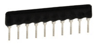
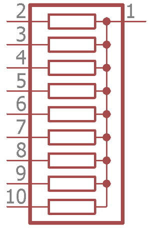
This is the symbol of the resistor net. Pin 1 is connected with the resistor pins, this pin needs to be connected at VCC for Pull-Up or to the Ground for Pull-down purposes. By using this SIP resistor, individual resistors are eliminated thus reducing the component counts and space in the board. It is available in various values, ranging from few ohms to kilo-ohms.

"hence preventing the logic level pin to getting shorted with the 5V source."
Re pulldown, it doesn't stop the logic pin being shorted to 5v at all. The logic pin IS connected directly to 5v regardless. This could be reworded.